

Arc extinguishing structure of miniature circuit breaker
A small circuit breaker and arc extinguishing technology, applied in circuit breaker parts, circuits, electrical components, etc., can solve the problems of arc extinguishing effect, reduce airflow stability, etc., achieve fast and convenient assembly, improve reliability, and ensure uniform effect
- Summary
- Abstract
- Description
- Claims
- Application Information
AI Technical Summary
Problems solved by technology
Method used
Image

Examples
Embodiment
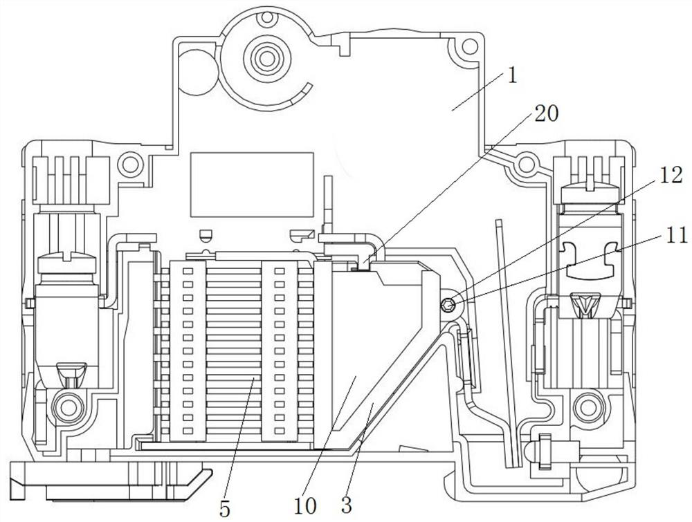
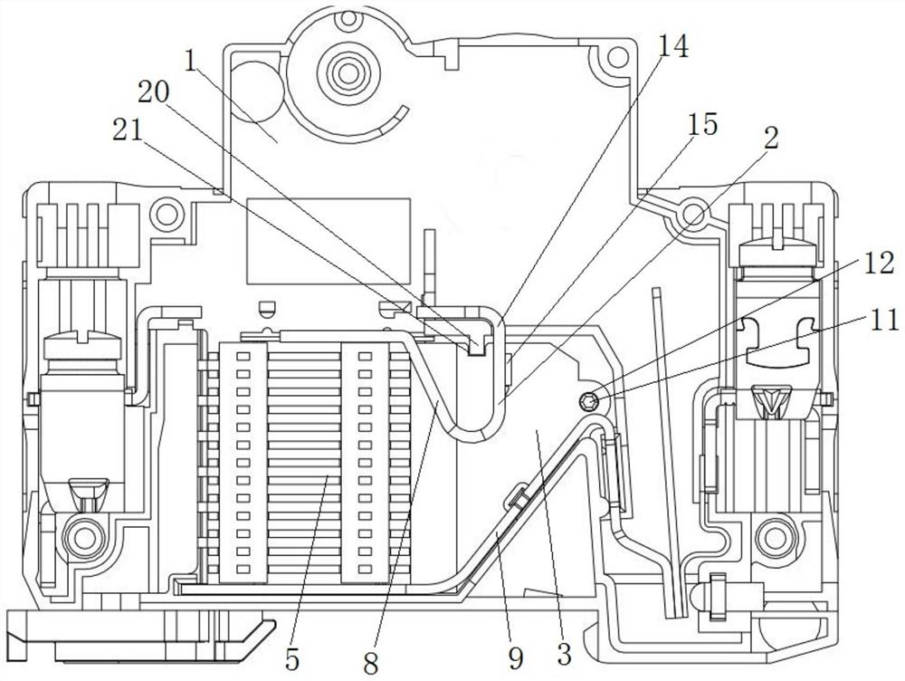
[0037] This embodiment provides a miniature circuit breaker, such as figure 1 and 2 As shown, it includes a housing 1 , and a conductive member 14 , an arc striker 4 , an arc shield 3 , a magnetic guide plate 10 and an arc extinguishing chamber 5 arranged on the housing 1 .
[0038] The conductive member 14 is located between the two arc shields 3, such as figure 2 and 4 As shown, it has an integrally bent static contact 2 and an arc-leading pin 8 connected to form, the static contact 2 is provided with a static contact 15, and the arc-leading pin 8 is from the static contact 2 to the arc extinguishing chamber 5 direction extension.
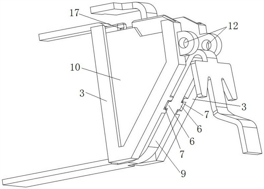
[0039] The arc striker 4 is arranged between the two arc dividers 3 , and a position limiting structure is provided between the arc striker 4 and the arc divider 3 to limit the position of the arc divider 3 . In this example, if image 3 and 8 As shown, the arc starting piece 4 is an arc starting piece 9 arranged on the lower side of the o...
PUM
 Abstract
Description
Claims
Application Information