Supercharge Your Innovation With Domain-Expert AI Agents!

Use of nanoparticles to tune index of refraction of layers of a polymeric matrix to optimize microoptic (MO) focus

A nanoparticle, refractive index technology, applied in the direction of nanotechnology, optics, optical components, etc. for materials and surface science, can solve the problem of imposing constraints on the performance characteristics of final products

Pending Publication Date: 2021-12-14
CRANE & CO
View PDF0 Cites 0 Cited by
  • Summary
  • Abstract
  • Description
  • Claims
  • Application Information

AI Technical Summary

Problems solved by technology

At the same time, the nature of the materials used, combined with the laws of physics used to construct micro-optical security devices, can impose constraints on the performance characteristics of the final product

Method used


Image

  • Use of nanoparticles to tune index of refraction of layers of a polymeric matrix to optimize microoptic (MO) focus
  • Use of nanoparticles to tune index of refraction of layers of a polymeric matrix to optimize microoptic (MO) focus
  • Use of nanoparticles to tune index of refraction of layers of a polymeric matrix to optimize microoptic (MO) focus

Examples


Embodiment Construction

[0026] discussed below Figure 1A to Figure 10B The various embodiments used to describe the principles of the disclosure in this patent document are by way of illustration only and should not be construed in any way as limiting the scope of the disclosure.

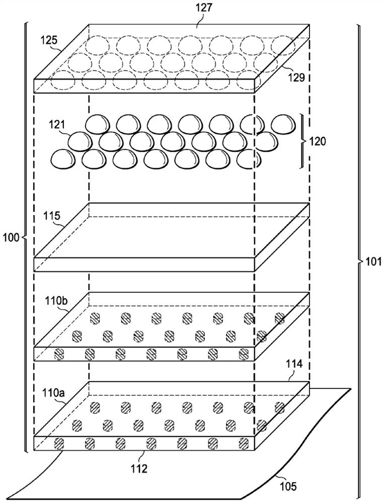
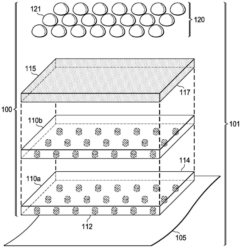
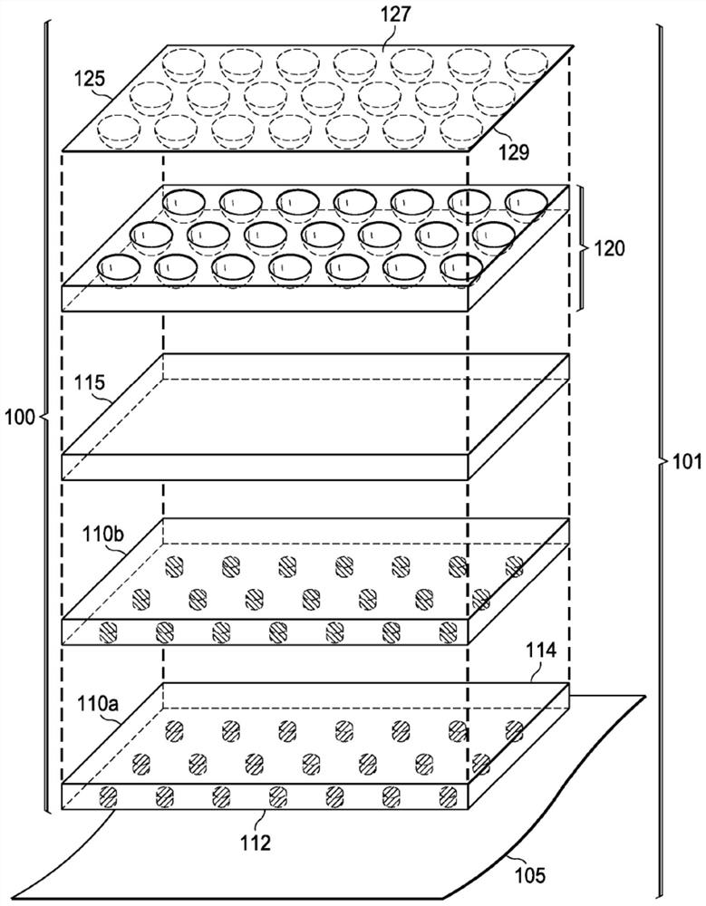
[0027] Figure 1A , Figure 1B and Figure 1C Examples of elements of micro-optical security devices and security documents including micro-optical security devices according to certain embodiments of the present disclosure are illustrated. for your convenience, Figure 1A , Figure 1B and Figure 1C Structural elements common to the examples are numbered identically (eg, substrate 105 ).

[0028] refer to Figure 1A As a non-limiting example, the micro-optical security device 100 and security document 101 may be constructed as Figure 1A A layered combination of some or all of the elements shown in the illustrative example of .

[0029] Such asFigure 1A As shown in the illustrative example of , security document 101...


PUM

PropertyMeasurementUnit
thicknessaaaaaaaaaa
widthaaaaaaaaaa
diameteraaaaaaaaaa

Abstract

A security device (100, 600, 700) includes one or more arrangements of image icons (100a, 110b, 615, 715), one or more arrangements of refractive image icon focusing elements (120, 605, 705), and a sealing layer (127, 600, 1005) which includes an organic resin and nanoparticles. Further, the one or more arrangements of refractive image icon focusing elements is disposed above the one or more arrangements of image icons such that a portion of the one or more arrangements of refractive image icon focusing elements forms a synthetic image of a portion of the one or more arrangements of image icons. Still further, the one or more arrangements of refractive image icon focusing elements contact the sealing layer along a non-planar boundary.

Description

technical field [0001] The present disclosure generally relates to improving the performance of security devices, such as micro-optical strips applied to or otherwise incorporated into security documents to provide an anti-counterfeiting mark of authenticity. More specifically, the present disclosure relates to, but is not limited to, the use of nanoparticles to tune the refractive index of a polymer matrix (sometimes referred to as "goo") used to form one or more layers of a micro-optical security device to optimize Micro optics ("MO") focusing. Background technique [0002] In many cases, the challenges of designing and manufacturing certain micro-optical security devices include balancing the trade-offs between achieving desired properties of the final product and the opportunities and constraints imposed by, for example, available manufacturing techniques and the laws of physics. For example, manufacturers of security documents such as banknotes, checks, and other docum...

Claims


Application Information

Patent Timeline
Patent Type & Authority Applications(China)
IPC IPC(8): B41M3/14B42D25/00B42D25/30B42D25/40D21H21/40
CPCD21H21/40B42D25/351B42D25/373G02B27/16B42D25/29B42D25/324B42D25/425B42D25/36D21H21/52D21H19/58D21H19/385B42D25/23B42D25/24B82Y30/00C08K3/105C08F265/06C08F283/065C08K3/22C08K3/30C08K2003/2227C08K2003/2241C08K2003/2244C08K2003/3036G02B1/041G02B3/0037
Inventor N·J·格滕斯J·D·戈斯内尔
Owner CRANE & CO
Features
  • R&D
  • Intellectual Property
  • Life Sciences
  • Materials
  • Tech Scout
  • Unparalleled Data Quality
  • Higher Quality Content
  • 60% Fewer Hallucinations
Learn More