Eureka AIR delivers breakthrough ideas for toughest innovation challenges, trusted by R&D personnel around the world.

Hybrid nanoparticles

a nanoparticle and hybrid technology, applied in the field of hybrid nanoparticles, can solve the problems of insufficient single-phase liquid cooling of high heat flux applications, inability to use water, and inferior thermo-physical properties of pure water

Inactive Publication Date: 2011-04-05
MOHAPATRA SATISH C +6
View PDF2 Cites 244 Cited by
  • Summary
  • Abstract
  • Description
  • Claims
  • Application Information

AI Technical Summary

Problems solved by technology

Water has excellent thermal properties such as a high latent heat of evaporation, specific heat and thermal conductivity, but is not adequate for single-phase liquid cooling of high heat flux applications.
In addition, water cannot be used in applications where ambient temperature may reach below 0° C. Water / glycol mixtures provide a low freezing point, but their thermo-physical properties are inferior compared to pure water.
However, their specific heat and thermal conductivity are far worse than water and glycol / water mixtures and they are extremely expensive (>$200 / gallon).
All these fluids do not have an in-built energy storage mechanism other than the sensible heat, i.e., specific heat capacity.
PCMs have been very successful in static / passive thermal management systems for example, thermal interface materials, body suits / vests, cold / thermal storage, but in heat transfer fluid applications there have been problems of mechanical damage, supercooling of the PCMs inside microcapsules, agglomeration, and blockage of the heat exchanger channels.
However, addition of nanoparticles to a fluid does not increase the specific heat capacity, i.e., the energy storage capacity of the base fluid.
Therefore, a nano-fluid may be able to dissipate higher heat fluxes, but it does not have good thermal storage or transport capability.
Heat transfer fluids currently available do not provide a high heat flux and have limited applications where high heat flux is required.
The technical challenge is to develop a water-based fluid with low freezing point and very high heat capacity and thermal conductivity.

Method used


Image

  • Hybrid nanoparticles
  • Hybrid nanoparticles
  • Hybrid nanoparticles

Examples


example 1

[0024]Step 1:Paraffin (PCM) is melted at 65° C. The melting point of the paraffin is 50° C. in this example.[0025]Step 2: Melted paraffin is added to water containing sodium stearic acid (an emulsifier) at 65° C. using high shear mixing to create an emulsion of the paraffin in water. Alternatively, paraffin can be added to water containing sodium stearic acid. Then the mixture can be heated to 65° C. and mixed by applying high shear to create an emulsion of the paraffin in water.[0026]Step 3: The resulting emulsion is cooled below the melting point of paraffin (for example to about 50° C.) to solidify the paraffin. The result is a dispersion of the paraffin core particles in the water medium.[0027]Step 4: The surfaces of the paraffin particles are sensitized by stannous chloride.[0028]Prepare the following mixture:[0029]40 ml / l HCl[0030]7.5 g / l stannous chloride[0031]Expose paraffin particles from Step 3 to the HCl / stannous chloride mixture, above, for 5 min.[0032]Step 5: The surfac...

example 2

[0046]Step 1: Paraffin (PCM) is melted at 65° C. The melting point of the paraffin is 50° C. in this example.[0047]Step 2: Melted paraffin is added to water containing sodium stearic acid (an emulsifier) at 65° C. using high shear mixing to create an emulsion of the paraffin in water. Alternatively, paraffin can be added to water containing sodium stearic acid. Then the mixture is heated to 65° C. and mixed by applying high shear to create an emulsion of the paraffin in water.[0048]Step 3: The resulting emulsion is cooled below the melting point of paraffin (for example to about 50° C.) to solidify the paraffin. The result is a dispersion of the PCM core particles in water medium.[0049]Step 4: Gold nanoparticles (about 1-10 nm) of an opposite charge to that of the paraffin are added to the dispersion.[0050]Step 5: Sodium stearic acid is added as a stabilizer and the gold particles are heteroflocculated on the paraffin particles by electrostatic attraction (due to opposite charges). ...

example 3

[0071]Step 1: Paraffin (PCM) is melted at 65° C. The melting point of the paraffin is 50° C. in this example)[0072]Step 2: Melted paraffin is added to water containing sodium stearic acid (an emulsifier) at 65° C. using high shear mixing to create an emulsion of the paraffin in water. Alternatively, paraffin can be added to water containing sodium stearic acid. Then the mixture can be heated to 65° C. and mixed by applying high shear to create an emulsion of the paraffin in water.[0073]Step 3: The resulting emulsion is cooled below the melting point of paraffin (50° C.) to solidify the paraffin. The result is a dispersion of the PCM core particles in water medium.[0074]Step 4: Polyvinyl pyrrolidone (polymer) is added to the aqueous phase and dissolved by stirring.[0075]Step 5: The resultant mixture is cooled to about 25° C. (below the Theta point of polyvinyl pyrrolidone). The polymer is adsorbed on the PCM surface to create a thin shell.[0076]The next step is to create the metal sh...


PUM

PropertyMeasurementUnit
diameteraaaaaaaaaa
thermal conductivityaaaaaaaaaa
diameteraaaaaaaaaa

Abstract

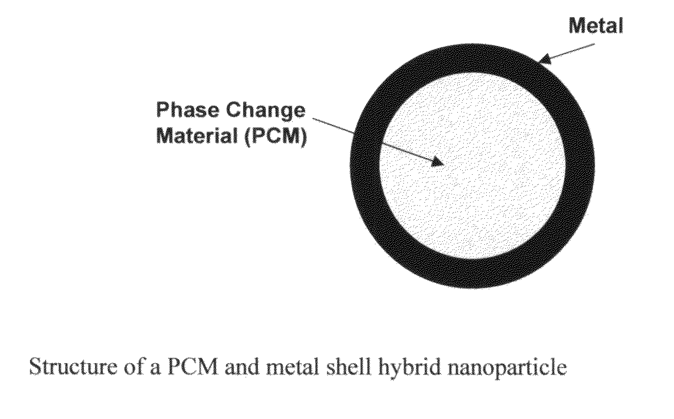
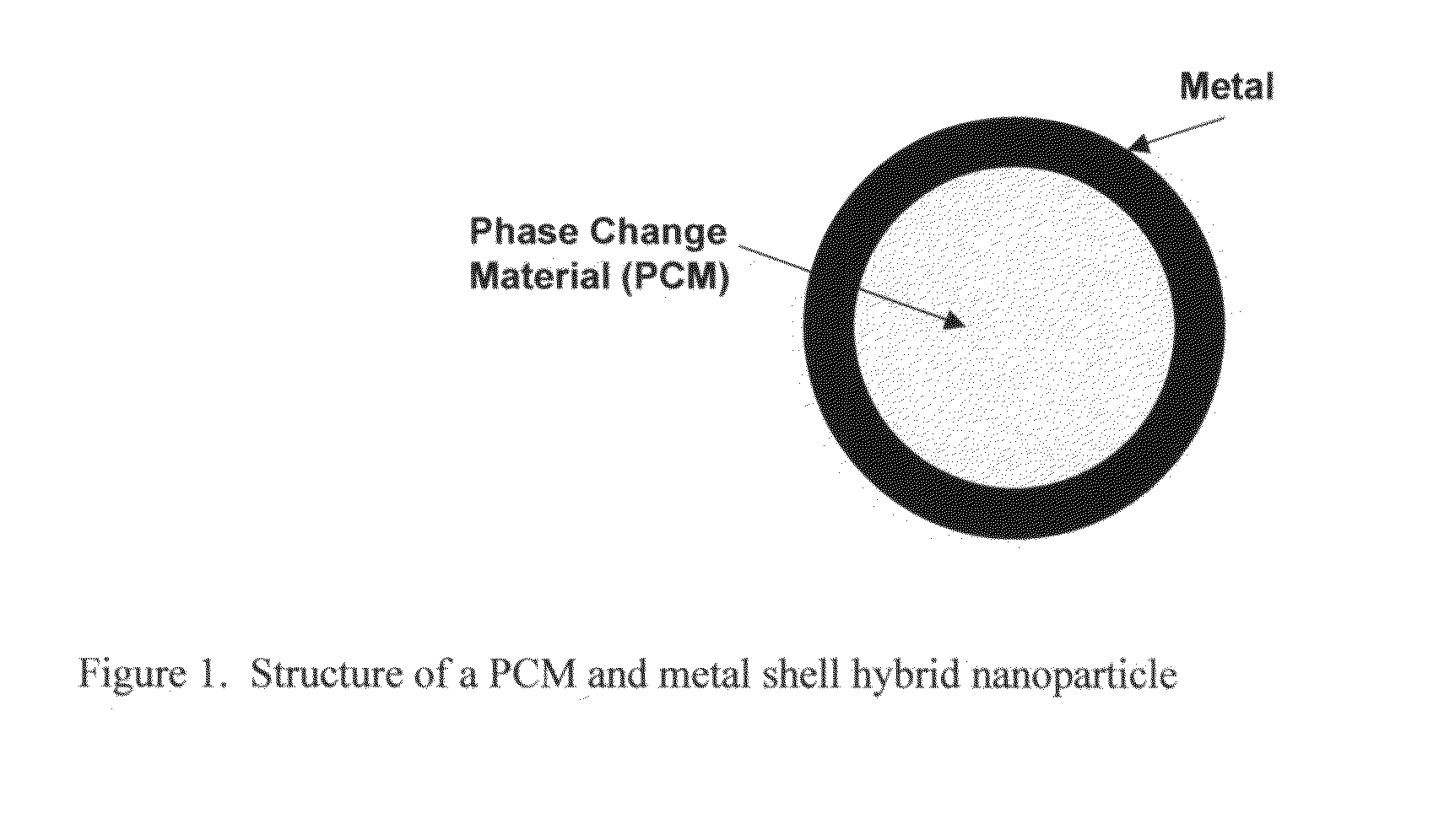
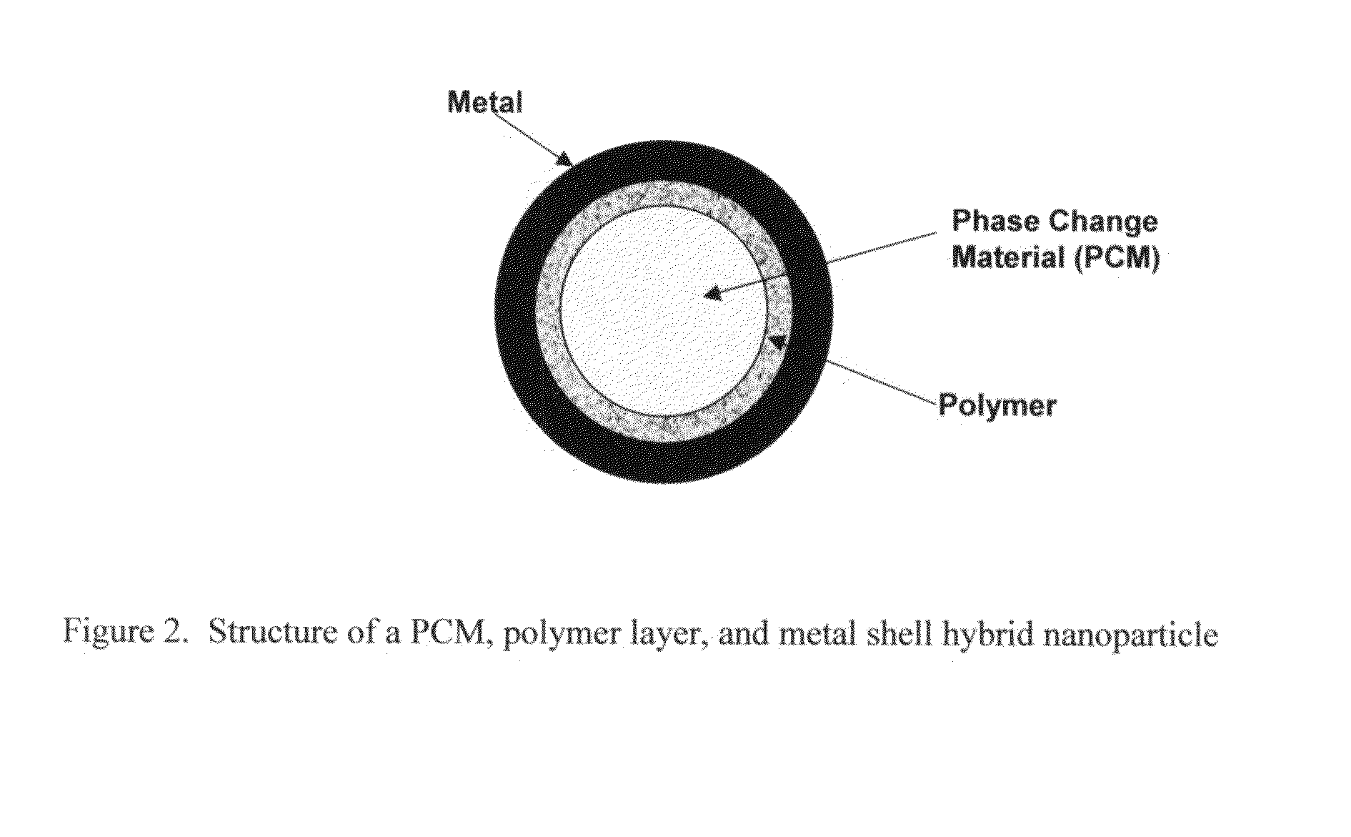
A method and composition for making hybrid nanoparticles and use of such nanoparticles are disclosed herein. In one embodiment of the invention, the hybrid nanoparticles comprise a phase change material (PCM) and a metal layer encapsulating the phase change material. In another embodiment of the invention, the hybrid nanoparticles comprise a phase change material, a polymer layer encapsulating the phase change material, and an outer metal layer encapsulating the polymer layer. In another embodiment of the invention, the hybrid nanoparticles comprise an inner core of a PCM encapsulated by a polymer shell containing embedded nanoparticles that have a high thermal conductivity.

Description

STATEMENT REGARDING FEDERALLY SPONSORED RESEARCH[0001]This invention is supported, in part, by the US Department of Defense, Small Business Innovation Research Grant, grant # FA8650-05-M-2506.[0002]This application claims the benefit of provisional application No. 60 / 839,092 titled Hybrid Nanoparticles, filed Aug. 21, 2006.BACKGROUND OF THE INVENTION[0003]Nanoparticles are particles with a diameter ranging from about 1 nm to 1000 nm. There are different types of nanoparticles available in the market place. Metals (such as copper, gold, and silver), metal oxides (such as zinc oxide, copper oxide), diamond and other forms of carbon have been used to make their respective nanoparticles. These particles have demonstrated applications in several fields such as drug-delivery, cosmetics formulations and heat transfer fluids.[0004]The important properties for a heat transfer fluid in relation to heat transfer capabilities are the following: specific heat capacity (Cp), thermal conductivity ...

Claims


Application Information

Patent Timeline
Patent Type & Authority Patents(United States)
IPC IPC(8): B32B5/16B32B15/04
CPCB01J13/04C09K5/10Y10T428/2998Y10T428/2991Y10T428/2989Y10T428/31678Y10T428/31692Y10T428/31801Y10T428/31909
Inventor MOHAPATRA, SATISH C.SUDOL, EDWARD DAVIDBIAN, KEJIANZHANG, LIDANIELS, ERIC SCOTTDIMONIE, VICTORIA LAURENTIAKLEIN, ANDREW
Owner MOHAPATRA SATISH C
Why Eureka
Eureka Blog
Learn More