Drawing tool box for architectural design

A technology for drawing tools and architectural design, applied in the field of toolboxes, which can solve the problems of a single toolbox structure, inability to protect tools, and the inability of toolboxes to provide drawing planes, etc.

Inactive Publication Date: 2021-12-17
JIANGXI NORMAL UNIVERSITY
View PDF0 Cites 0 Cited by
  • Summary
  • Abstract
  • Description
  • Claims
  • Application Information

AI Technical Summary

Problems solved by technology

[0004] In view of the problems mentioned in the background technology, the purpose of the present invention is to provide a drawing toolbox for architectural design, to solve the problem that the common toolbox structure is relatively single, the tools cannot be effectively protected, and the common toolbox cannot provide a drawing plane The problem

Method used


Image

  • Drawing tool box for architectural design
  • Drawing tool box for architectural design
  • Drawing tool box for architectural design

Examples


Embodiment 1

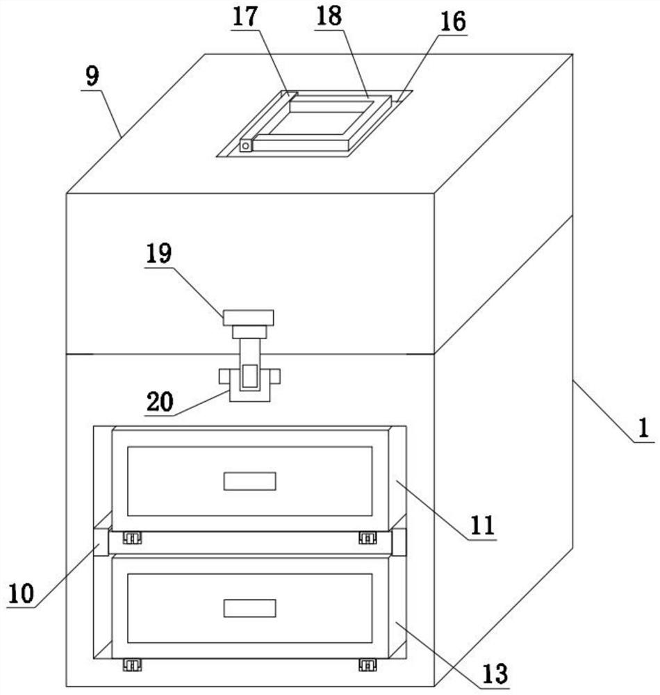
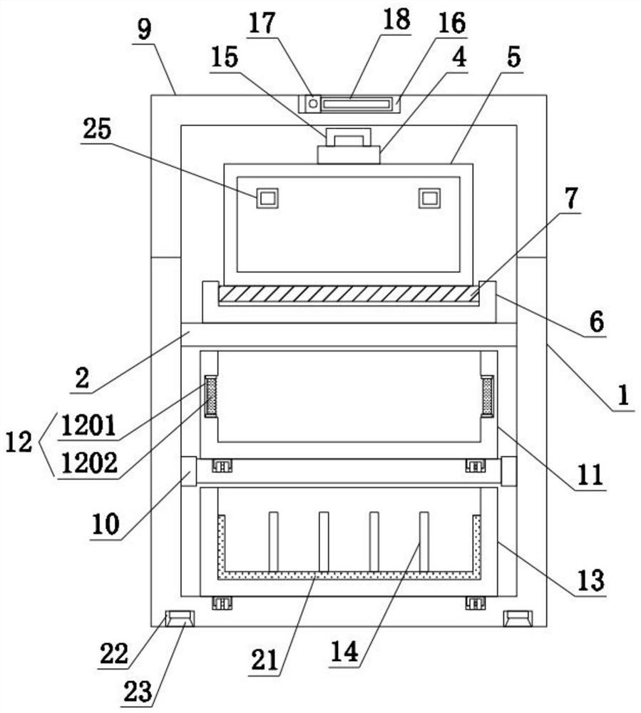
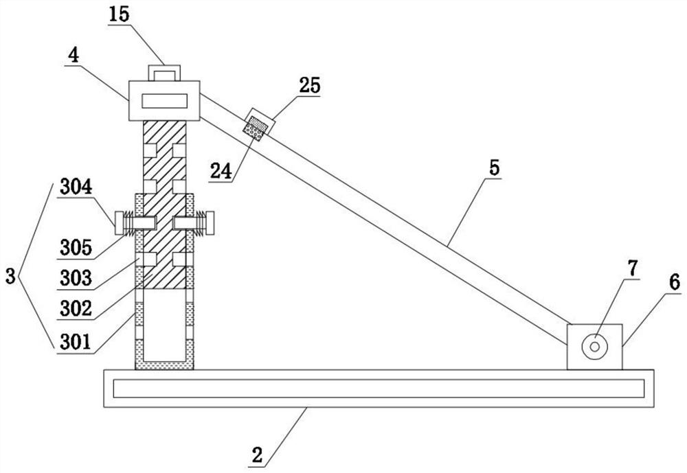
[0034] refer to Figure 1-4 , a drawing toolbox for architectural design described in this embodiment, comprising a box body 1, the inner upper end of the box body 1 is fixedly connected with a first partition 2, and the top rear end of the first partition 2 is fixedly equipped with a telescopic mechanism 3. The top of the telescopic mechanism 3 is fixedly connected with the connection base 4, the front lower end of the connection base 4 is fixedly connected with the support plate 5, the top front end of the first partition 2 is fixedly connected with the mounting base 6, and the inside of the mounting base 6 is fixedly installed with Rotating shaft 7, the other end of support plate 5 is connected with rotating shaft 7, and the back upper end of casing 1 is hinged with case cover 9 by hinge 8, and the inner middle end of casing 1 is fixedly connected with second dividing plate 10, and the second dividing plate The top of the board 10 is slidably connected with the first drawer...

Embodiment 2

[0037] refer to image 3 , on the basis of Embodiment 1, in order to achieve the purpose of height adjustment, this embodiment has innovatively designed the height adjustment method. Specifically, the telescopic mechanism 3 includes a first pole 301, a second pole 302, and a through hole 303 , a limit pin 304, a return force spring 305, the top rear end of the first partition 2 is fixedly connected with a first pole 301, and the inside of the first pole 301 is plugged with a second pole 302, and the first pole 301 and The corresponding positions on the left and right sides of the second pole 302 are provided with a plurality of groups of through holes 303, and the inside of the through holes 303 is inserted with the limit pin 304, and the retaining ring of the limit pin 304 is fixedly connected with the first pole 301. There is a return spring 305, a first pole 301 and a second pole 302 are provided, the second pole 302 is plugged into the inside of the first pole 301, and the...

Embodiment 3

[0041] refer to figure 2 In this embodiment, on the basis of Embodiment 2, in order to achieve the purpose of dehumidification, this embodiment has innovatively designed the dehumidification method. Specifically, the dehumidification mechanism 12 includes an installation groove 1201, a dehumidification filter element 1202, and the interior of the first drawer 11 Mounting grooves 1201 are provided on the left and right sides, and a dehumidification filter element 1202 is clamped inside the installation groove 1201. The installation groove 1201 is provided. The installation groove 1201 is used for installing the dehumidification filter element 1202. Air is absorbed so as to ensure that the drawings stored in the first drawer 11 are always in a dry state.

[0042] refer to figure 1 , in order to achieve the purpose of closing the toolbox, the front lower end of the case cover 9 in this embodiment is fixedly connected with an upper buckle 19, and the front upper end of the box b...


PUM


Abstract

The invention discloses a drawing tool box for building design. The drawing tool box comprises a box body, wherein a first partition plate is fixedly connected to an upper end of the interior of the box body, a telescopic mechanism is fixedly installed at a rear end of the top of the first partition plate, a connecting base is fixedly connected to the top of the telescopic mechanism, and a supporting plate is fixedly connected to a lower end of a front face of the connecting base; a front end of the top of the first partition plate is fixedly connected with a mounting base, a rotating shaft is fixedly mounted in the mounting base, the other end of the supporting plate is connected with the rotating shaft, a box cover is hinged ton an upper end of a back face of the box body through a hinge, the middle end in the box body is fixedly connected with a second partition plate, and the top of the second partition plate is slidably connected with a first drawer; and a dehumidification mechanism is fixedly mounted in the first drawer. By the adoption of the structure, one end of the supporting plate is connected with the connecting base, the other end of the supporting plate is connected with the rotating shaft in the mounting base, when the connecting base ascends, one end of the supporting plate is driven to ascend, and therefore a purpose of adjusting an inclination angle of the supporting plate is achieved.

Description

technical field [0001] The invention belongs to the field of toolboxes, in particular to a drawing toolbox for architectural design. Background technique [0002] Architectural design means that before the construction of a building, the designer, according to the construction task, makes an overall assumption in advance of the construction process and the problems that may occur during the construction process, draws up the methods and plans to solve these problems, and draws up and document expression. [0003] When doing the drawing work of architectural design, it is often necessary to use a toolbox to carry various drawing tools, but most of the common toolboxes on the market have a single structure, and the protection effect on the tools is poor, and the drawing design is carried out in the environment such as the construction site However, due to the poor environment, the plane required for drawing cannot be provided, which will easily lead to the user's drawing mist...

Claims


Application Information

Patent Timeline
IPC IPC(8): A47B83/00A47B63/02A47B67/04A47B81/00A47B27/14A47B88/969A47B97/00B01D53/26
CPCA47B83/00A47B27/14A47B63/02A47B67/04A47B81/00A47B88/969A47B97/00B01D53/261
Inventor 陈俊奇
Owner JIANGXI NORMAL UNIVERSITY
Why Eureka
Try Eureka