
Grouting anchor rod structure and using method thereof

A technology of grouting anchors and anchors, which is applied in the installation of anchors, foundation structure engineering, excavation, etc., can solve the problem of insufficient stability of the anchor body, and achieve the effect of reducing the possibility and increasing the stability

Pending Publication Date: 2021-12-17
中铁建设集团华北工程有限公司
View PDF12 Cites 0 Cited by
  • Summary
  • Abstract
  • Description
  • Claims
  • Application Information

AI Technical Summary

Problems solved by technology

[0005] In order to improve the problem of insufficient fixation of the bolt body, the application provides a grouted bolt structure and its use method

Method used


Image

  • Grouting anchor rod structure and using method thereof
  • Grouting anchor rod structure and using method thereof
  • Grouting anchor rod structure and using method thereof

Examples


Embodiment Construction

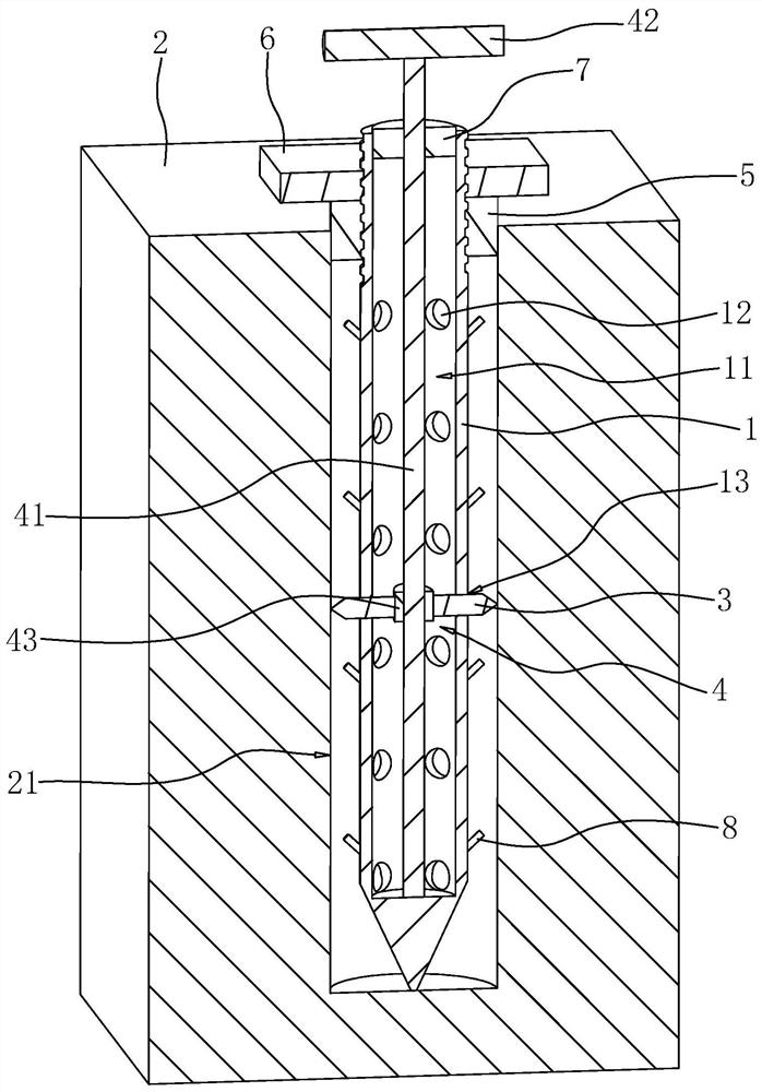
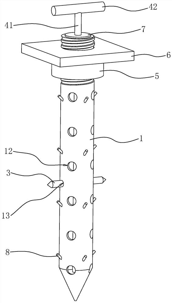
[0038] The following is attached Figure 2-5 The application is described in further detail.

[0039] The embodiment of the present application discloses a grouting anchor structure.

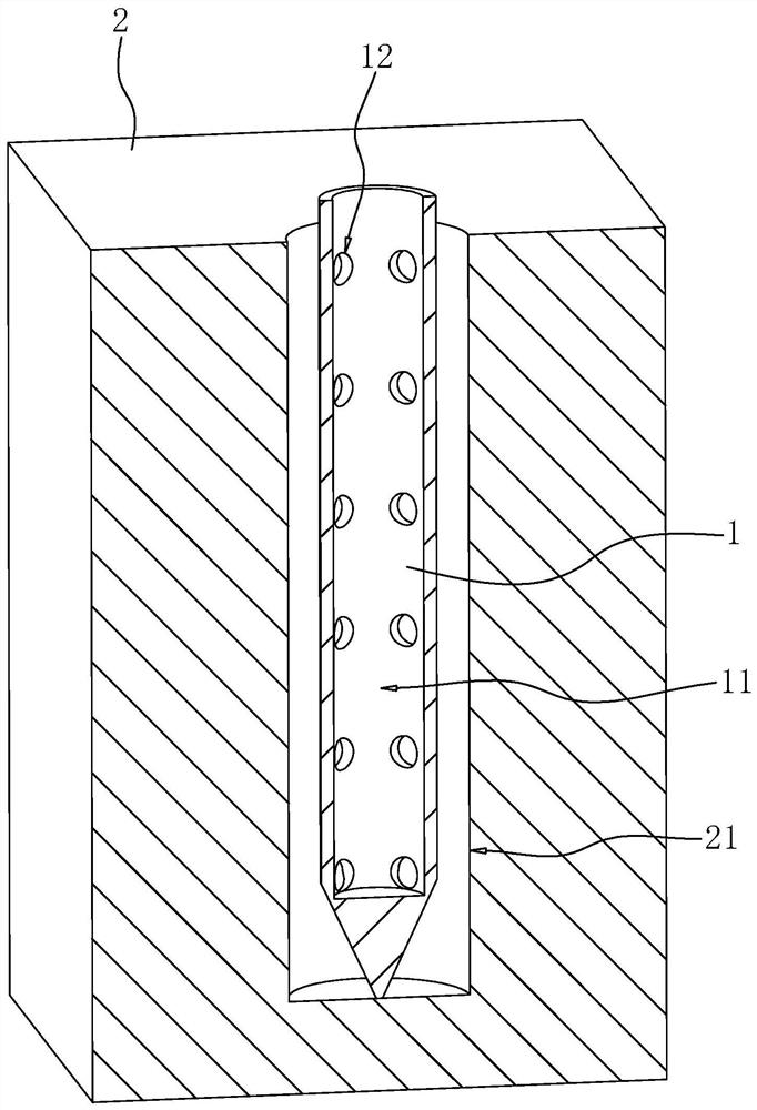
[0040] Such as figure 2 and image 3 As shown, the grouting anchor structure includes an anchor body 1, the upper surface of the anchor body 1 is provided with a grouting channel 11 inwardly, and the outer wall of the anchor body 1 is provided with several grouting holes 12 inwardly, and the grouting holes 12 communicates with the grouting channel 11. The ground 2 is provided with a reserved hole 21 downward, and the bolt body 1 is vertically inserted into the reserved hole 21 .

[0041] The vertical outer wall of the bolt body 1 is provided with a pair of connection holes 13 inwardly, and the connection holes 13 are communicated with the grouting channel 11 . Abutment rods 3 are plugged into the connection holes 13 , and the abutment rods 3 are arranged horizontally. One end of the abutme...


PUM


Abstract

The invention relates to the field of building construction, in particular to a grouting anchor rod structure. The grouting anchor rod structure comprises an anchor rod body, a grouting channel is formed in the anchor rod body, a plurality of grouting holes communicating with the grouting channel are formed in the anchor rod body, and the anchor rod body is connected with a reserved hole formed in the ground in an inserted mode. A connecting hole communicating with the grouting channel is inwards formed in the outer wall of the anchor rod body, an abutting rod is slidably inserted into the connecting hole, and the abutting rod is connected with an abutting assembly which enables the end, away from the grouting channel, of the abutting rod to be inserted into soil. The invention further discloses a using method of the grouting anchor rod. The grouting anchor rod structure has the effect of improving the stability when the anchor rod body is fixed.

Description

technical field [0001] The present application relates to the field of building construction, in particular to a grouting anchor structure and an application method thereof. Background technique [0002] Grouting anchor is a common tool in tunnel engineering, slope treatment engineering, and coal mine roadway engineering, and is used to support the rock surface for the first excavation. [0003] Such as figure 1 As shown, an existing grouting anchor includes an anchor body 1, the interior of the anchor body 1 is hollow, and the space inside the anchor body 1 is a grouting channel 11, and the grouting channel 11 runs through the top of the anchor body 1. On the surface, the outer surface of the bolt body 1 is provided with a plurality of grouting holes 12 , and the grouting holes 12 are communicated with the grouting channel 11 . The ground 2 is provided with a reserved hole 21 downwards, insert the bolt body 1 vertically downwards into the reserved hole 21, and then inject...

Claims


Application Information

Patent Timeline
Patent Type & Authority Applications(China)
IPC IPC(8): E21D21/00E21D20/02E02D17/20E02D5/74
CPCE21D21/0026E21D21/008E21D20/02E02D17/20E02D5/74
Inventor 费耀明鱼双键应丹林张江华熊桂林
Owner 中铁建设集团华北工程有限公司
Learn More