Centrifugal blade wheel blade tip clearance matching method

A centrifugal impeller and blade tip clearance technology, which is applied in the direction of mechanical clearance measurement, instruments, and measuring devices, can solve the problems of difficult selection of centrifugal impeller blade tip clearance, inaccurate calculation method of size chain, and inability to select reference points, etc., to achieve Avoid cumulative tolerances, small errors, and easy adjustment

Pending Publication Date: 2021-12-17
CHINA HANGFA SOUTH IND CO LTD
View PDF0 Cites 0 Cited by
  • Summary
  • Abstract
  • Description
  • Claims
  • Application Information

AI Technical Summary

Problems solved by technology

Since the blade tip of the centrifugal impeller 1 is streamlined, it is impossible to select the reference point corresponding to the impeller cover 3 and the rotor 4, the calculation method of the size chain is not accurate enough, and due to structural limitations, the lead pressing method or feeler gauge method cannot be used. inspection, and the precision metering cycle is long, so the selection of centrifugal impeller tip clearance becomes a difficult problem

Method used


Image

  • Centrifugal blade wheel blade tip clearance matching method
  • Centrifugal blade wheel blade tip clearance matching method
  • Centrifugal blade wheel blade tip clearance matching method

Examples


Embodiment Construction

[0032] The embodiments of the present invention will be described in detail below with reference to the accompanying drawings, but the present invention can be implemented in various ways defined and covered below.

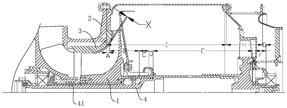
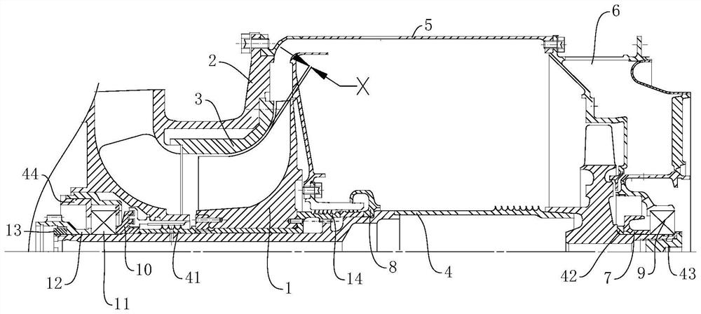
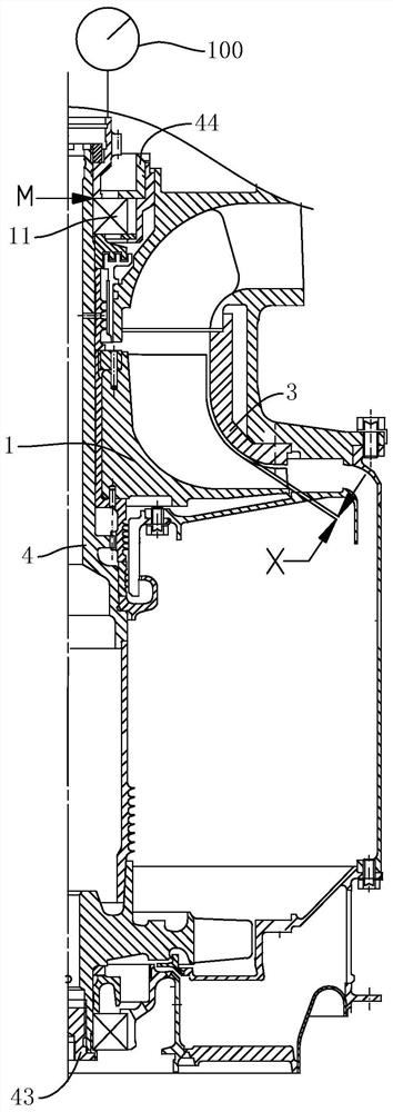
[0033] Such as figure 2 As shown, the embodiment of the present invention provides a centrifugal impeller blade tip clearance matching method, and the two fulcrum bearings of the engine rotor are associated with the engine stator and the rotor 4 ( Figure 5 ), the rotor 4 is pretended to be installed in the engine casing, and the axial movement of the rotor 4 is used to move the rotor 4 axially so that the centrifugal impeller 1 ( Figure 4 ) and the impeller cover 3 are in the first tight fit state, and the first axial moving distance of the rotor 4 is measured in the first tight fit state; according to the design requirements of the component structure, by tightening the compression nut of the bearing pressure plate 44, the rotor 4. Move the axial direction fo...


PUM


Abstract

The invention discloses a centrifugal blade wheel blade tip clearance matching method, which comprises the following steps of: associating two fulcrum bearings of an engine rotor with an engine stator and a rotor, assembling the rotor in an engine case in a false way, axially moving the rotor to enable a centrifugal blade wheel and a blade wheel cover to be in a first tight fit state by utilizing the axial movement characteristic of the rotor, and measuring a first axial movement distance in the first tight fit state; according to the structural design requirement of the assembly, enabling the rotor to axially move forwards to a limit position by screwing down a compression nut of a bearing pressing plate so as to make a front bearing ring and a bearing cover plate be in a second tight fit state, and measuring a second axial movement distance in the second tight fit state, wherein the absolute value of the difference between the first axial movement distance and the second axial movement distance is the blade tip clearance value X of the centrifugal blade wheel; and if the blade tip clearance value X is not within a specified range, grinding a front adjusting pad to meet the clearance requirement. The method can simplify the measurement calculation, reduce the measurement error and improve the assembly precision.

Description

technical field [0001] The invention relates to the technical field of aero-engine assembly, in particular to a method for selecting and matching the blade tip clearance of a centrifugal impeller. Background technique [0002] When assembling components, the gap between parts is often used by lead pressing method, feeler gauge inspection method, dimensional chain calculation, precision measurement and other methods. The method of guaranteeing the clearance of centrifugal impeller tip is usually the method of dimensional chain calculation, but the centrifugal impeller tip is For streamlined structure, it is necessary to find the reference point corresponding to the matching stator parts by using the size chain calculation. Due to structural limitations, the reference points corresponding to the stator and rotor cannot be selected at the same time, resulting in inaccurate impeller tip clearance and centrifugal As an important part of the aeroengine compressor, the impeller dir...

Claims


Application Information

Patent Timeline
Patent Type & Authority Applications(China)
IPC IPC(8): G01B5/14G01B5/00
CPCG01B5/14G01B5/003
Inventor 杜霞王龙段一帆林进朱林
Owner CHINA HANGFA SOUTH IND CO LTD
Why Eureka
Try Eureka