Layered quantitative sampling device for petroleum detection

A quantitative sampling and petroleum technology, applied in sampling devices and other directions, can solve problems such as difficulty in control, and achieve the effect of easy cleaning and manpower saving

Inactive Publication Date: 2021-12-17
张丽娟
View PDF1 Cites 7 Cited by
  • Summary
  • Abstract
  • Description
  • Claims
  • Application Information

AI Technical Summary

Problems solved by technology

[0004] This oil testing and sampling device realizes oil sampling by placing the rubber dropper in the oil, and then the extrusion device retracts and squeezes the rubber ball on the top of the rubber dropper. Although this operation is simple and convenient, it needs The staff manually controls, and it is difficult to control the amount of oil taken. Therefore, it is necessary to design a layered quantitative sampling device for oil detection that can quantitatively sample oil.

Method used


Image

  • Layered quantitative sampling device for petroleum detection
  • Layered quantitative sampling device for petroleum detection
  • Layered quantitative sampling device for petroleum detection

Examples


Embodiment 1

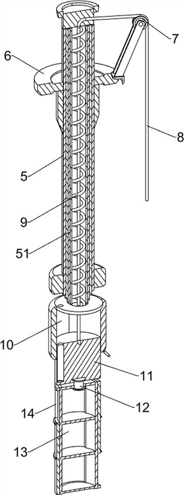
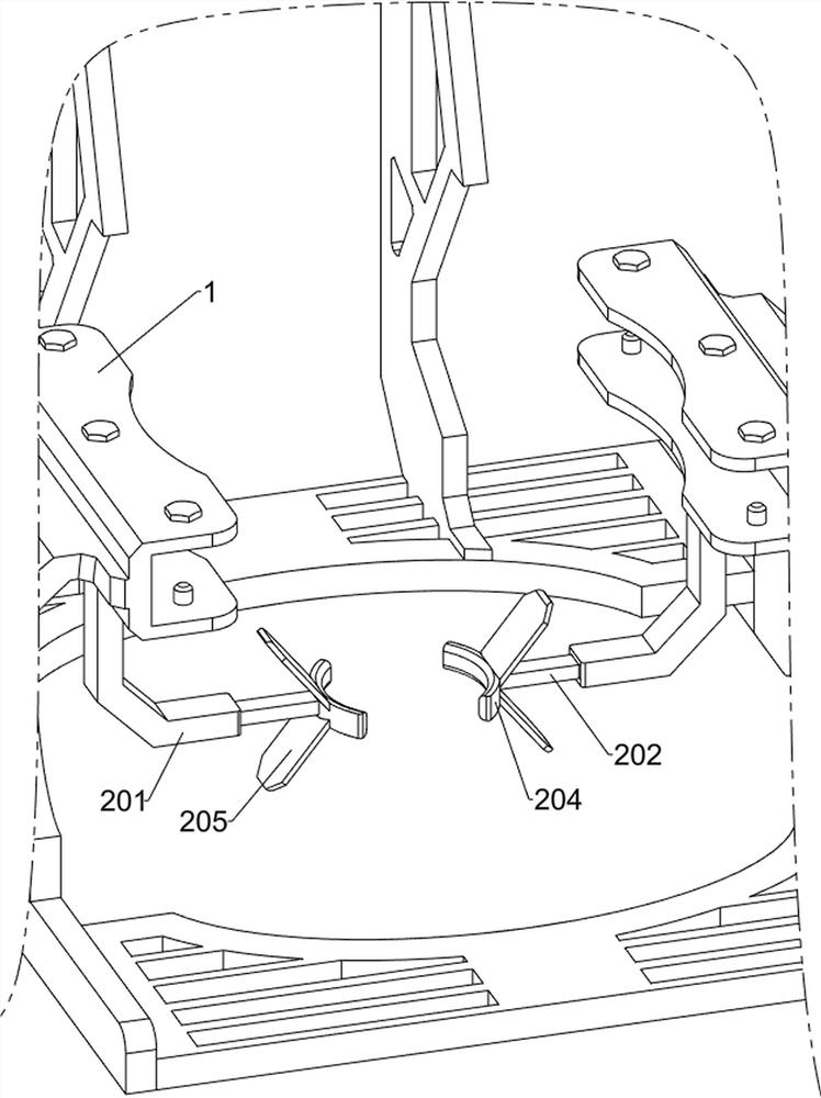
[0040] A layered quantitative sampling device for petroleum detection, such as Figure 1-7 As shown, it includes a fixed frame 1, a first connecting plate 2, a connecting frame 3, a fixed plate 4, a fixed rod 5, a first telescopic rod 51, a second connecting plate 6, a pulley 7, a stay cord 8, and a first spring 9. , the third connecting plate 10, the first connecting block 11, the first rotating shaft 12, the charging frame 13, the casing 14, the lifting mechanism 15 and the rotating mechanism 16, the first connecting plate 2 is installed in the middle part of the fixed frame 1, and the fixed frame 1 The left and right sides of the middle part are equipped with a connecting frame 3, the connecting frame 3 is located at the outside of the first connecting plate 2, a fixed plate 4 is installed between the two connecting frames 3 tops, and a fixed rod 5 is installed in the middle of the fixed plate 4, inside the fixed rod 5 The first telescopic rod 51 is connected, the second co...

Embodiment 2

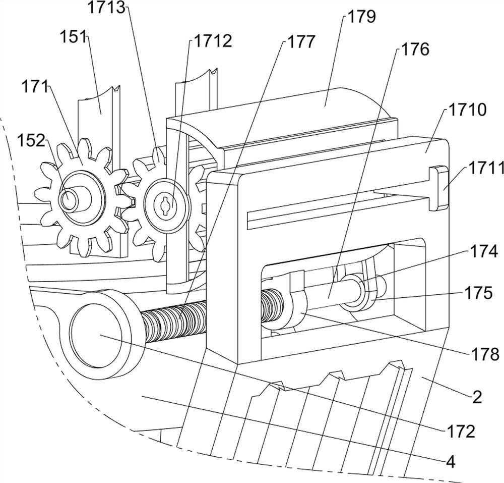
[0045] On the basis of Example 1, such as figure 1 , Figure 8 , Figure 9 and Figure 10 As shown, power mechanism 17 is also included, and power mechanism 17 includes spur gear 171, the 6th connecting plate 172, motor 173, belt pulley 174, flat belt 175, second rotating shaft 176, screw mandrel 177, nut 178, the 7th connection Plate 179, guide plate 1710, slider 1711, second telescopic rod 1712, long gear 1713 and missing gear 1714, the right side of the first connecting shaft 152 is equipped with a flat gear 171, the flat gear 171 is located on the left side of the chain 154, and the left and right sides of the fixed plate 4 The sixth connecting plate 172 is installed on both sides, and a motor 173 is installed on the top of the sixth connecting plate 172 on the left side. The motor 173 is used to provide driving force. A long gear 1713 and a missing gear 1714 are respectively installed on the bar 1712, the missing gear 1714 is located on the left side of the long gear 1...

Embodiment 3

[0048] On the basis of Example 2, such as figure 1 and Figure 11 As shown, an anti-slip mechanism 18 is also included, and the anti-slip mechanism 18 is used to fix the first connecting shaft 152 to prevent the first connecting shaft 152 from rotating on its own. and the third spring 184, the ninth connecting plate 181 is installed between the middle parts of the two fourth connecting plates 151, and the middle part of the ninth connecting plate 181 is slidingly connected with an extrusion ball 182, and the middle part of the first connecting shaft 152 is equipped with a rotating plate 183 , a plurality of grooves are evenly spaced on the rotating plate 183, and the extrusion ball 182 is matched with the groove, and the extrusion ball 182 can be snapped into the groove, and a third spring is connected between the extrusion ball 182 and the ninth connecting plate 181 184 , the top end of the third spring 184 is connected with the ninth connecting plate 181 , and the bottom en...


PUM


Abstract

The invention relates to a sampling device, in particular to a layered quantitative sampling device for petroleum detection. The invention provides the layered quantitative sampling device for petroleum detection, which can be used for quantitatively sampling petroleum. The layered quantitative sampling device for petroleum detection comprises a fixing frame, a first connecting plate, connecting frames, a fixing plate, a fixing rod, a first telescopic rod, a second connecting plate, a pulley, a pull rope, a first spring, a third connecting plate, a first connecting block, a first rotating shaft, a loading frame, a shell, a lifting mechanism and a rotating mechanism, wherein the first connecting plate is arranged on the inner side of the middle part of the fixing frame, and the connecting frames are installed on the left and right sides of the middle part of the fixing frame. Through the lifting mechanism, a worker can move the loading frame to a petroleum sampling position only by rotating a rocker to sample petroleum, the sampling amount of the petroleum can be controlled through the rotating mechanism, and excessive petroleum is prevented from being taken.

Description

technical field [0001] The invention relates to a sampling device, in particular to a layered quantitative sampling device for oil detection. Background technique [0002] Petroleum is one of the most common and consuming energy sources in modern society. Nowadays, oil exploitation has been carried out in many places. Before oil exploitation, it is usually necessary to sample the oil in the mining area, and use the oil sample to detect the oil in the mining area. For the quality of oil, at present, machines are mainly used to carry out oil sampling work, but most of the existing sampling machines are relatively large and complicated to operate. [0003] The patent application number is CN201720742931.8 A petroleum testing and sampling device, including a bearing seat, a fixing device, a base, a handle, a rubber dropper, an extrusion device, a guide plate, a top plate and a rotating rod, and the base is provided with a fixing device and The bearing seat, the fixing device is...

Claims


Application Information

Patent Timeline
Patent Type & Authority Applications(China)
IPC IPC(8): G01N1/10
CPCG01N1/10
Inventor 张丽娟
Owner 张丽娟
Why Eureka
Try Eureka