
Patsnap Eureka
For R&D, Patsnap Eureka makes reading and utilizing patents & technical documents easy.
Patsnap Eureka AIR
Designed for self-driven R&D workflows. Generate viable solutions, solve complex R&D challenges, empower your innovation with AI.

Patsnap Eureka Materials
Designed for material experts only. Revolutionize your material R&D, from search, analyze, to developing new materials.

TechResearch
Generate reliable direction feasibility study reports for your R&D in just a few steps.

TechSeek
Discover and master advanced knowledge NOW. Basics, ideas, possibilities, all at once.

TechMind
As an expert in R&D Theories, TechMind can generates customized viable solutions instantly.

TechRisk
Analyze your overall solution with one click, know your potential R&D risks in advance.

TechMonitor
Get weekly tech updates, stay abreast of the latest tech innovations and key insights.
Antenna surface pitch angle adjusting and locking rotary table and portable antenna
A technology of antenna surface and pitch angle, which is applied to antennas, folding antennas, antenna parts, etc., can solve problems such as poor stability, poor adjustment accuracy, and difficult positioning, and achieve simple, easy operation, and easy storage Effect
- Summary
- Abstract
- Description
- Claims
- Application Information
AI Technical Summary
Problems solved by technology
Method used
Image

Examples
Embodiment 1
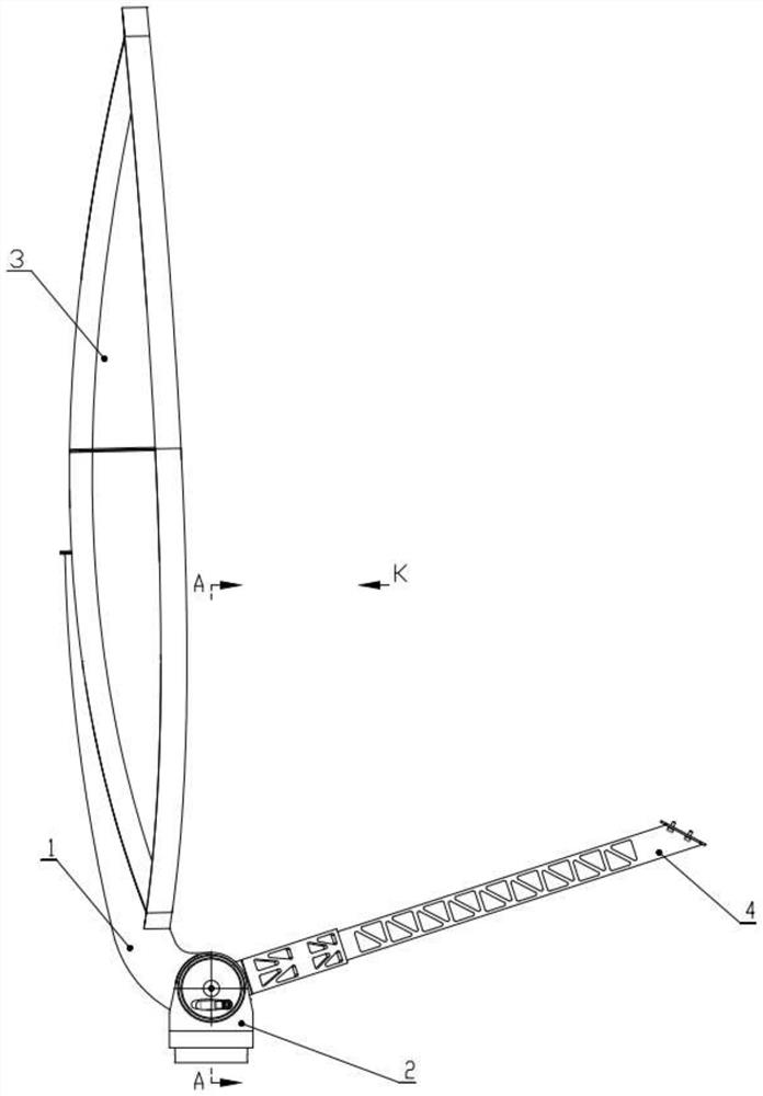
[0040] Such as Figure 1-8 As shown, this embodiment provides an antenna plane pitch angle adjustment and locking turntable, which includes an antenna support 1 and a support assembly, and the support assembly includes a support 2, a pitch transmission shaft 10, an adjustment assembly and a locking assembly;
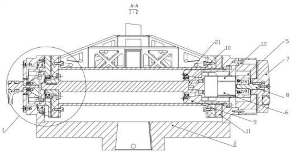
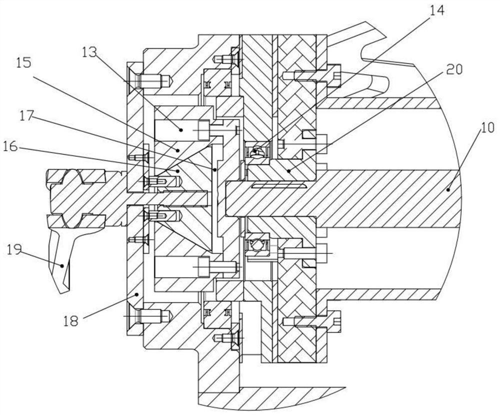
[0041] See figure 2 , the right end of the support 2 is provided with a right pitch lug 5, and the right pitch lug 5 is rotatably connected to the antenna bracket 1, and a reducer flange 9 is fixed inside the right pitch lug 5 And the planetary reducer 6, the right end of the planetary reducer 6 is provided with a reducer end cover 12, and the right side of the reducer end cover 12 is provided with a folding handwheel 7, and the folding handwheel 7 and the planetary reducer 6 are connected by hand The wheel connection shaft 8 is axially connected, and the output shaft of the planetary reducer 6 can be driven to rotate by rotating and folding the hand wheel 7. The outpu...
Embodiment 2
[0047] Such as figure 1 and Figure 6 As shown, on the basis of Embodiment 1, this embodiment discloses a portable antenna, including an antenna surface 3, a feed support arm 4, and the antenna surface pitch angle adjustment and locking turntable disclosed in Embodiment 1. The antenna main body 31 and the five-split 32 are spliced, and then the antenna surface 3 is fixedly connected to the antenna support 1, and the feed support arm 4 is fixedly connected to the left side plate 29 and the right side plate 11, and the end of the feed support arm 4 is provided with Feed connection board 27 .
[0048] When a kind of portable antenna disclosed in this embodiment is stored, such as Figure 9 and Figure 11 As shown, except for the main body 31 of the antenna surface 3, the other five-split lobes 32 are all removed. The pin head of the self-locking knob 25 is not inserted into the pin hole 30, and the pitch angle between the antenna bracket 1 and the feed arm 4 can be adjusted b...
PUM
 Abstract
Description
Claims
Application Information
 - R&D Engineer
- R&D Manager
- IP Professional
- Industry Leading Data Capabilities
- Powerful AI technology
- Patent DNA Extraction
Browse by: Latest US Patents, China's latest patents, Technical Efficacy Thesaurus, Application Domain, Technology Topic, Popular Technical Reports.
© 2024 PatSnap. All rights reserved.Legal|Privacy policy|Modern Slavery Act Transparency Statement|Sitemap|About US| Contact US: help@patsnap.com