Paint spraying device

A one-to-one, component technology, applied in the direction of spraying devices, spray booths, etc., can solve the problems of simultaneous painting of multiple metal pipe fittings, low painting efficiency, and unfavorable production needs of enterprises, so as to achieve high market application value and improve painting efficiency , easy-to-use effects

Active Publication Date: 2021-12-21
江苏克莱德激光技术有限责任公司
View PDF10 Cites 1 Cited by
  • Summary
  • Abstract
  • Description
  • Claims
  • Application Information

AI Technical Summary

Problems solved by technology

Although the above-mentioned technical solution can realize the painting of metal pipe fittings to a certain extent, it cannot realize simultaneous painting of multiple metal pipe fittings, resulting in low painting efficiency, which is not conducive to the production needs of enterprises

Method used


Image

  • Paint spraying device
  • Paint spraying device
  • Paint spraying device

Examples


specific Embodiment 1

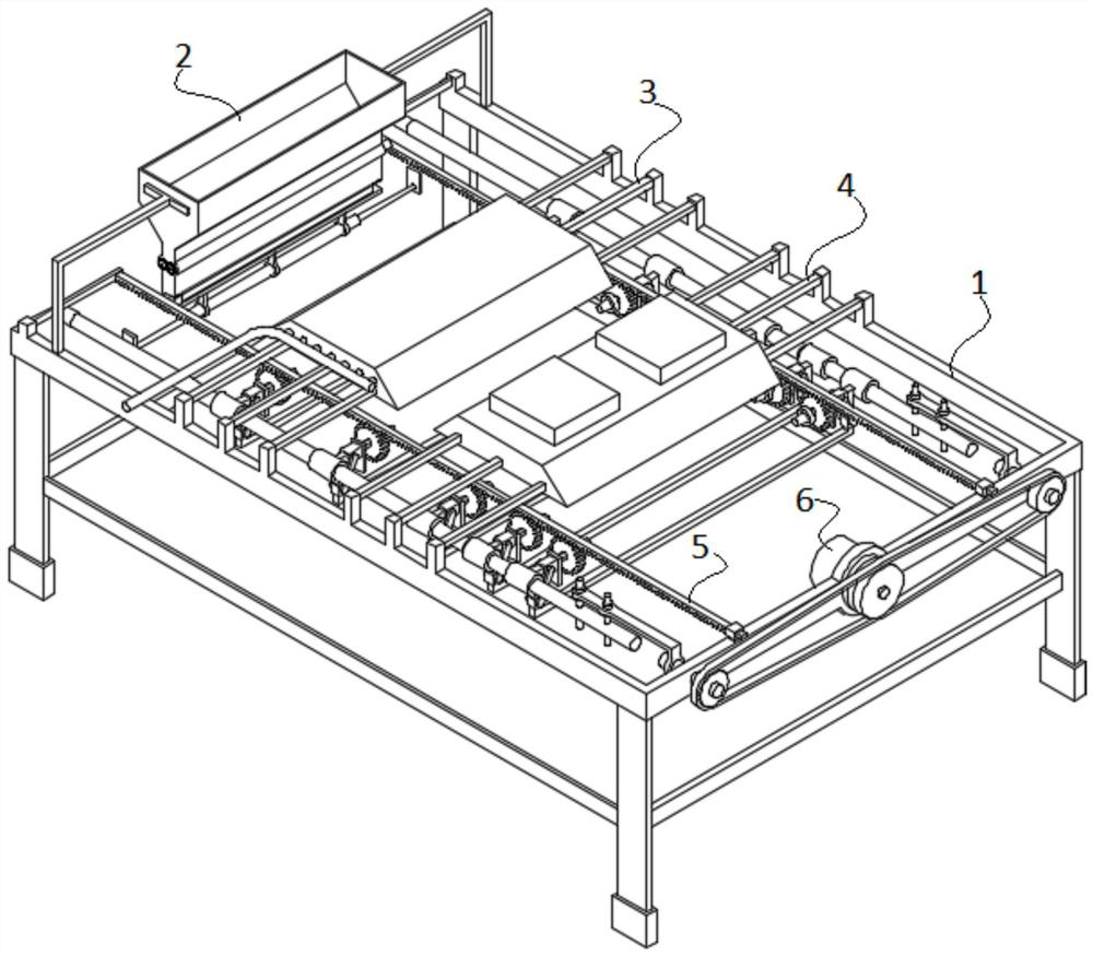
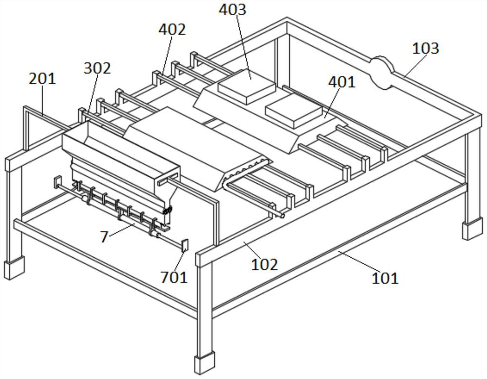
[0033] see Figure 1-Figure 4 As shown, the present invention is a painting device, including a support assembly 1; the support assembly 1 includes a support frame 101; a pair of side support beams 102 are horizontally fixed on the support frame 101; The beams 103 are connected; between the supporting beams 102 on both sides, a feeding assembly 2, a painting assembly 3 and a drying assembly 4 are arranged side by side along the length direction; the drying assembly 4 is arranged between the painting assembly 3 and the middle beam 103; The beam 103 is equipped with a transport assembly 5 . The material is taken from the feeding assembly 2 through the conveying assembly 5, and then the material is carried by the feeding assembly 2 through the painting assembly 3 and the drying assembly 4 to realize painting and drying.

specific Embodiment 2

[0035] This embodiment is further optimized on the basis of specific embodiment one, specifically as follows:

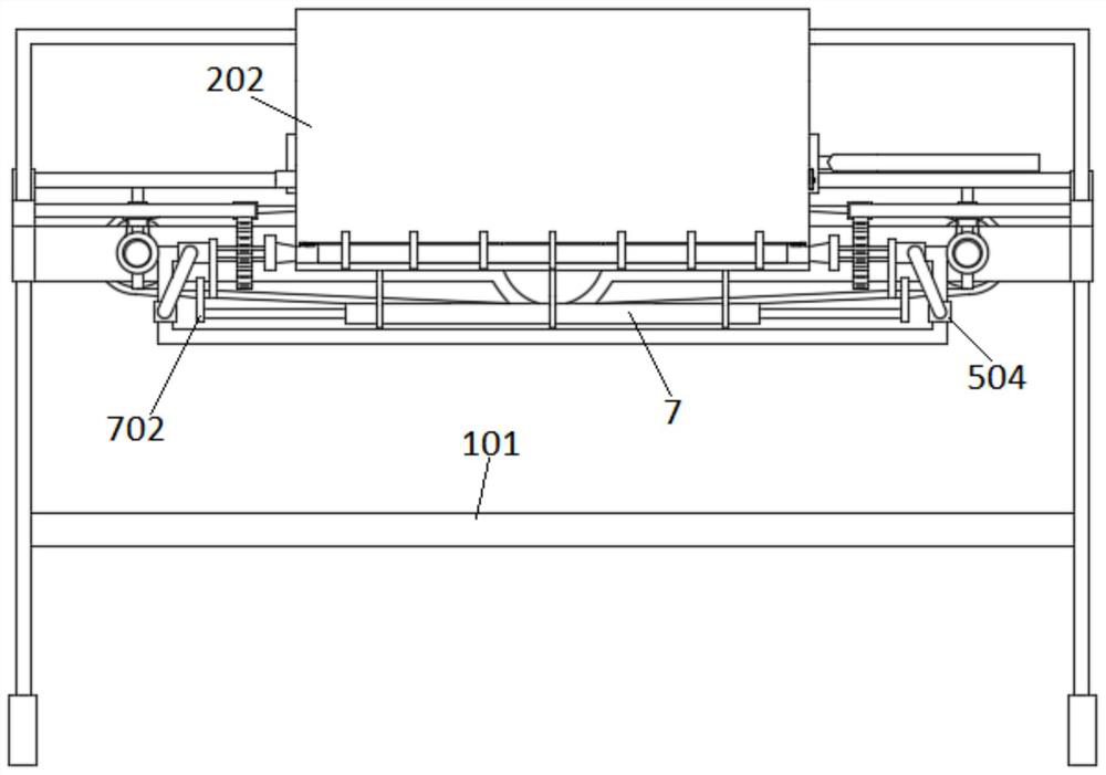
[0036] Such as image 3 and Figure 5-Figure 7As shown, the feeding assembly 2 includes a pair of first support rods 201 respectively fixed on the support beams 102 on both sides; a storage box 202 is fixed between the two first support rods 201; the upper part of the storage box 202 is open Structure; the bottom of the material storage box 202 has a sliding material channel 2021; the external expansion chamber 2022 is provided in the material sliding channel 2021; a pair of drive shafts 203 are installed in the external expansion chamber 2022 along the length direction; the outer wall of the drive shaft 203 There are a plurality of paddles 2031 fixed in the radial direction; two drive shafts 203 are fixed with rotating gears 2032 toward the same end; One end of one end is connected on the output shaft of a rotating motor 2033; The rotating motor 2033 is fixed on t...

specific Embodiment 3

[0040] This embodiment is further optimized on the basis of specific embodiment two, specifically as follows:

[0041] Such as Figure 4 and Figure 9-Figure 10 As shown, the transport assembly 5 includes a pair of guide racks 501 arranged side by side between the support beams 102 on both sides; A pair of drive screw mandrels 502 are installed for rotation between the bars 501; the drive screw mandrels 502 are arranged in parallel with the guide rack 501; the drive screw mandrels 502 are sleeved with a plurality of screw nuts 5021 side by side; Corresponding two nuts 5021 are connected by a bearing rod 503; the bearing rod 503 includes a pair of horizontal guide sections 5031 respectively fixed on the outer walls of the two nuts 5021; set vertically; the ends of the two horizontal guide sections 5031 are fixed with a vertical guide section 5032; the lower ends of the two vertical guide sections 5032 are connected by a connecting section 5033; the horizontal guide section 50...


PUM


Abstract

The invention discloses a paint spraying device, and relates to the technical field of pipe machining. The device comprises a supporting assembly; the supporting assembly comprises a supporting frame. A pair of side supporting beams are horizontally fixed on the supporting frame; and the ends, facing the same direction, of the supporting beams on the two sides are connected through a middle beam. A feeding assembly, a paint spraying assembly and a drying assembly are arranged between the supporting beams on the two sides side by side in the length direction. A material conveying assembly is arranged on the middle beam. Materials are taken from the feeding assembly through the material conveying assembly, then the materials are driven by the feeding assembly to sequentially pass through the paint spraying assembly and the drying assembly, paint spraying and drying are achieved, the structural design is reasonable, use is convenient and fast, paint spraying and drying can be conducted on multiple metal pipes, the paint spraying efficiency of the metal pipes is effectively improved, and the device has high market application value.

Description

technical field [0001] The invention belongs to the technical field of pipe processing, in particular to a paint spraying device. Background technique [0002] In the prior art, in order to prevent the surface of metal pipe fittings from rusting, a layer of antirust paint is usually coated on the surface of metal pipe fittings. The Chinese invention whose authorized notification number is CN213255352U discloses a metal pipe fitting painting equipment. After the metal pipe fitting is placed between the first support frame and the second support frame, the third electric telescopic rod is used to drive the spray head along the axis of the metal pipe fitting. direction movement, so as to realize the painting of metal pipe fittings. Although the above-mentioned technical solution can realize the painting of metal pipe fittings to a certain extent, it cannot realize simultaneous painting of multiple metal pipe fittings, resulting in low painting efficiency, which is not conduciv...

Claims


Application Information

Patent Timeline
Patent Type & Authority Applications(China)
IPC IPC(8): B05B13/02B05B16/20
CPCB05B13/0207B05B13/0221B05B16/20
Inventor 车朝杰
Owner 江苏克莱德激光技术有限责任公司
Why Eureka
Try Eureka