Heating device and evaporation device using same

A heating device and equipment technology, used in lighting and heating equipment, vacuum evaporation coating, sputtering coating and other directions, can solve problems such as uneven heating, achieve stable evaporation rate, improve accuracy, and increase stability. Effect

Pending Publication Date: 2021-12-21
SYSKEY TECH CO LTD
View PDF4 Cites 0 Cited by
  • Summary
  • Abstract
  • Description
  • Claims
  • Application Information

AI Technical Summary

Problems solved by technology

[0004] One of the objectives of the present invention is to provide a heating device and its applicable evaporation equipment, wherein the heating device includes a heat conduction element, which can improve the problem of uneven heating of materials during heating, make the evaporation rate more stable, and further improve the coating efficiency. quality

Method used


Image

  • Heating device and evaporation device using same
  • Heating device and evaporation device using same
  • Heating device and evaporation device using same

Examples


Embodiment Construction

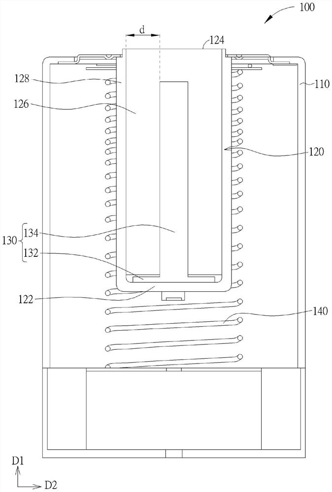
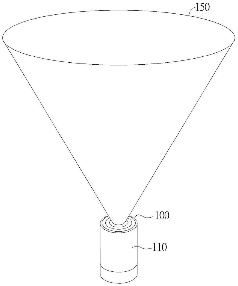
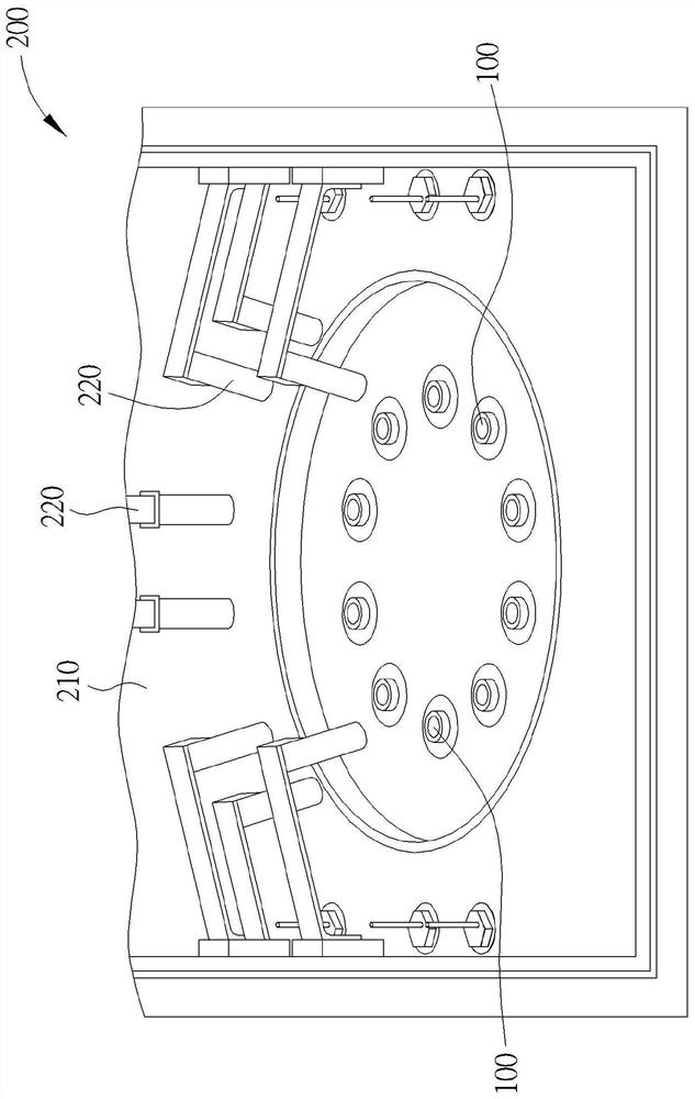
[0032] The present invention can be understood by referring to the following detailed description in conjunction with the drawings. It should be noted that, in order to make the readers easy to understand and the drawings are concise, the drawings of the present invention only draw at least a part of the heating device or the evaporation equipment and certain elements in the drawings are not drawn to actual scale. In addition, the quantity and size of each element in the drawings are only for illustration, and are not intended to limit the scope of the present invention.

[0033] Throughout this specification and the appended claims, certain terms will be used to refer to particular elements. Those skilled in the art should understand that evaporation equipment manufacturers or the industry may use different names to refer to the same component. This document does not intend to distinguish between those elements that have the same function but have different names. In the fo...


PUM


Abstract

A heating device and an evaporation device using the same are provided. The heating device includes a crucible, a heat conducting element and a heating element. The crucible includes a bottom surface, an opening opposite to the bottom surface and an accommodation space for accommodating a to-be-evaporated material. The heat conducting element is disposed in the accommodation space of the crucible and disposed on the bottom surface and extending towards the opening. The heating element is disposed adjacent to the crucible.

Description

technical field [0001] The invention relates to a heating device and its applicable evaporation equipment, in particular to a heating device including a heat conduction element and its applicable evaporation equipment. Background technique [0002] The evaporation process is a widely used coating technology. In the existing technology, a common practice is to use an evaporation machine to heat the material to be evaporated in a thermal evaporation chamber, so that the material evaporates and disperses in the chamber, and then adheres. Or onto the object to be deposited to form a coating film on the surface of the object to be deposited. [0003] However, when the material is heated, the part of the material that is close to the heating source is more likely to be heated and evaporated, while the part that is relatively far away from the heating source is less likely to be heated, so that the material may be in an unstable state of evaporation due to uneven heating, which in...

Claims


Application Information

Patent Timeline
Patent Type & Authority Applications(China)
IPC IPC(8): C23C14/26C23C14/12C23C14/54
CPCC23C14/26C23C14/12C23C14/543F27B14/14F27B2014/0831F27B14/20F27B14/10
Inventor 吴学宪
Owner SYSKEY TECH CO LTD
Why Eureka
Try Eureka