Cooling device of new energy automobile

A technology of new energy vehicles and cooling devices, applied in electric vehicles, battery/fuel cell control devices, vehicle components, etc., can solve the problems of difficult disassembly, inconvenient disassembly, and poor practicability, so as to reduce the difficulty of disassembly and improve the convenience of disassembly degree of effect

Active Publication Date: 2021-12-21
深圳电通信息技术有限公司
View PDF12 Cites 0 Cited by
  • Summary
  • Abstract
  • Description
  • Claims
  • Application Information

AI Technical Summary

Problems solved by technology

[0004] (2) The battery cooling device is integrated and fixed. When the cooling device dissipates heat from the battery, it will accumulate a lot of dust. It needs to be cleaned frequently to ensure the efficient heat dissipation of the equipment. However, the battery mostly adopts a horizontal fixed structure, which cannot Perform multi-angle cleaning without disassembly, which is less practical
[0005] The battery cooling device adopts integrated fixing, because the air circulation in the cooling device is fast, and there is a certain humidity near the cooling pipe, the traditional screw fixing will appear rusty, which makes it very inconvenient to disassemble, and even needs to use electric A screwdriver is required for disassembly, which is difficult to disassemble

Method used


Image

  • Cooling device of new energy automobile
  • Cooling device of new energy automobile
  • Cooling device of new energy automobile

Examples


Embodiment Construction

[0035] The following will clearly and completely describe the technical solutions in the embodiments of the present invention with reference to the accompanying drawings in the embodiments of the present invention. Obviously, the described embodiments are only part of the embodiments of the present invention, not all of them. Based on the embodiments of the present invention, all other embodiments obtained by persons of ordinary skill in the art without creative efforts fall within the protection scope of the present invention.

[0036] It should be noted that all directional indications (such as up, down, left, right, front, back...) in the embodiments of the present invention are only used to explain the relationship between the components in a certain posture (as shown in the accompanying drawings). Relative positional relationship, movement conditions, etc., if the specific posture changes, the directional indication will also change accordingly.

[0037] In addition, in t...


PUM


Abstract

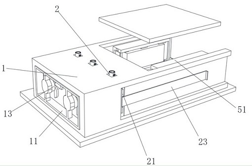
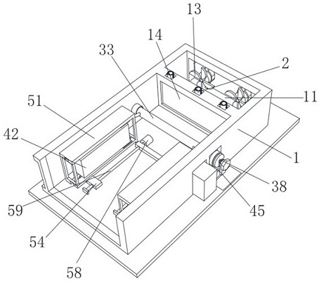
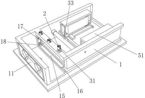
The invention discloses a cooling device of a new energy automobile, and relates to the technical field of new energy automobiles. The cooling device comprises a cooling bottom plate, wherein an air inlet frame is fixedly mounted on the inner side wall of the cooling bottom plate, an air inlet fan is mounted on the inner side wall of the air inlet frame, a filtering dismounting device, a water pipe quick dismounting device and a battery turning device are arranged on the cooling bottom plate, the water pipe quick dismounting device is located between the filtering dismounting device and the battery turning device, and the filtering dismounting device comprises an outer rotating sleeve and a filter screen. When a sliding rotating shaft moves to the other end of an inner sliding rail of a battery pack frame, the battery pack just rotates by 90 degrees in the battery pack frame, meanwhile, the sliding rotating shaft moves into a rectangular clamping groove formed in an inner rotating plate, and a battery pack does not need to be disassembled, compared with the condition that when a traditional battery pack is cleaned, due to the fact that the traditional battery pack is mostly fixed through horizontal screws, disassembly and cleaning are needed during cleaning, great inconvenience is achieved, and even the battery pack is damaged due to collision during disassembly.

Description

technical field [0001] The invention relates to the technical field of new energy vehicles, in particular to a cooling device for new energy vehicles. Background technique [0002] For example, the Chinese invention patent discloses "new energy vehicle battery management equipment", publication number: CN111674251A, the modular design of the battery pack is convenient for personnel to remove and replace the corresponding battery pack and can realize efficient insertion and removal of the battery pack in a timely manner. power on and off, but this battery cooling arrangement has the following disadvantages: [0003] (1) The battery cooling device is integrated and fixed. When the user needs to clean the battery, it needs to be disassembled as a whole, which is very inconvenient. [0004] (2) The battery cooling device is integrated and fixed. When the cooling device dissipates heat from the battery, it will accumulate a large amount of dust, and it needs to be cleaned freque...

Claims


Application Information

Patent Timeline
Patent Type & Authority Applications(China)
IPC IPC(8): H01M10/613H01M10/625H01M10/6554H01M10/6556H01M10/6563H01M50/244H01M50/249B60L58/26
CPCH01M10/613H01M10/625H01M10/6554H01M10/6556H01M10/6563H01M50/244H01M50/249B60L58/26Y02E60/10Y02T10/70
Inventor 谢翠华
Owner 深圳电通信息技术有限公司
Why Eureka
Try Eureka