Supercharge Your Innovation With Domain-Expert AI Agents!

Cutting device for transmission optical fiber and cutting method thereof

A technology for transmitting optical fibers and cutting devices, applied in the coupling of optical waveguides, metal processing and other directions, can solve problems such as uneven end faces, and achieve the effect of reducing the generation of debris, ensuring a cutting environment, and a good cutting environment

Active Publication Date: 2021-12-24
南京中枢讯飞信息技术有限公司
View PDF7 Cites 0 Cited by
  • Summary
  • Abstract
  • Description
  • Claims
  • Application Information

AI Technical Summary

Problems solved by technology

However, the currently used cutting device uses a high-speed rotating cutting blade to achieve the cutting effect, but the rotating cutting blade will form cutting lines on the end face of the optical fiber, resulting in uneven end face

Method used


Image

  • Cutting device for transmission optical fiber and cutting method thereof
  • Cutting device for transmission optical fiber and cutting method thereof
  • Cutting device for transmission optical fiber and cutting method thereof

Examples


Embodiment Construction

[0060] The present invention will be further described below in conjunction with the accompanying drawings and specific embodiments.

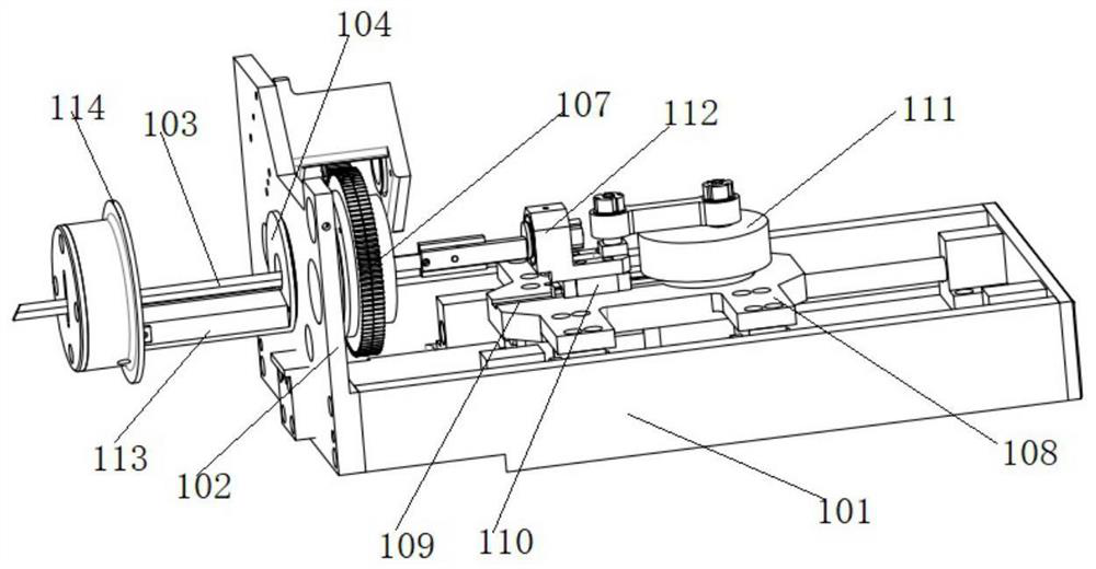
[0061] In the prior art, the cutting blade is generally rotated by the driving mechanism to act on the end face of the communication optical fiber. Although the high-speed rotating cutting blade achieves the cutting effect, the rotating cutting blade will form cutting lines on the end face of the optical fiber. , resulting in uneven end faces.

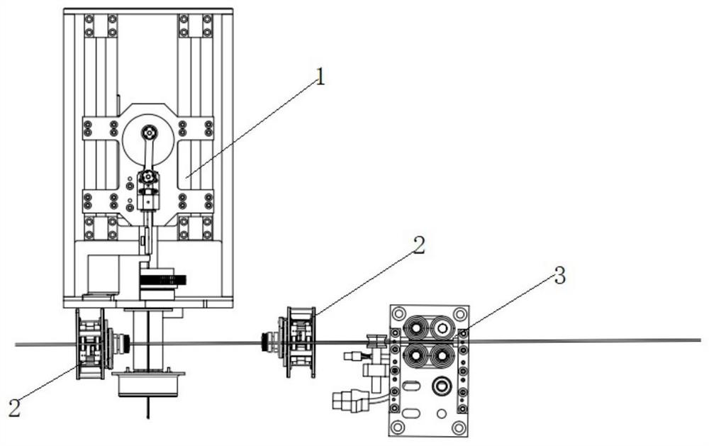
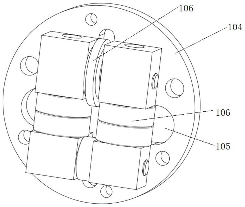
[0062] Therefore, in order to solve the above-mentioned technical problems, this embodiment discloses a cutting device for optical fiber transmission, such as figure 1 As shown, including: a rack, define one end of the rack as the input end, and the other end as the output end. That is to say, when cutting the communication optical fiber, the active end of the communication optical fiber enters from the input end, and outputs from the output end after cutting.

[0063] In a further embodiment, it also...


PUM


Abstract

The invention discloses a cutting device for a transmission optical fiber and a cutting method thereof, and belongs to the technical field of communication optical fibers. The cutting device comprises a cutting mechanism, a lifting mechanism and at least two groups of clamping mechanisms, wherein the cutting mechanism is mounted on a rack and is close to an output end; the cutting mechanism is provided with a cutting part for realizing inclined cutting according to requirements; the lifting mechanism is arranged on the opposite surface of the cutting mechanism; the lifting mechanism is provided with a lifting table; the at least two groups of clamping mechanisms are arranged on the lifting platform side by side; the at least two groups of clamping mechanisms are arranged to clamp the transmission optical fiber at the same time and enable the clamped transmission optical fiber to be suspended on the cutting part; during cutting, the lifting mechanism drives the clamping mechanisms to move downwards, the clamped transmission optical fiber moves downwards synchronously and acts on the cutting part, and cutting is completed. According to the cutting device, blade cutting is used for replacing rotary cutting in the prior art, the phenomenon that cutting lines are formed on the end face of the optical fiber through a cutting blade, and consequently the end face is uneven is avoided, generation of chippings is reduced, and a good cutting environment is guaranteed.

Description

technical field [0001] The invention belongs to the technical field of communication optical fibers, and in particular relates to a cutting device and a cutting method for transmission optical fibers. Background technique [0002] At present, communication optical fibers have been popularized, and the preparation of high-quality communication optical fibers is based on the flat end faces of the optical fibers, that is, only two optical fibers with flat end faces can achieve better fusion splicing. However, the currently used cutting device uses a high-speed rotating cutting blade to achieve the cutting effect, but the rotating cutting blade will form cutting lines on the end face of the optical fiber, resulting in uneven end face. Contents of the invention [0003] In order to solve the technical problems in the above-mentioned background technology, the present invention provides a cutting device and a cutting method for optical fiber transmission. [0004] The present i...

Claims


Application Information

Patent Timeline
Patent Type & Authority Applications(China)
IPC IPC(8): B26D1/06B26D5/08B26D7/02B26D7/06G02B6/25
CPCB26D1/06B26D5/086B26D7/02B26D7/06G02B6/25Y02P40/57
Inventor 张春华唐春玲
Owner 南京中枢讯飞信息技术有限公司
Features
  • R&D
  • Intellectual Property
  • Life Sciences
  • Materials
  • Tech Scout
  • Unparalleled Data Quality
  • Higher Quality Content
  • 60% Fewer Hallucinations
Learn More