
Grouting structure for sleeve valve pipe

A sleeve valve pipe and grouting technology, which is applied in the field of geotechnical engineering grouting, can solve problems affecting soil layer reinforcement and seepage prevention, pressure reduction, pipe jamming, etc.

Active Publication Date: 2021-12-24
TENGDA CONSTR GROUP CORP
View PDF5 Cites 0 Cited by
  • Summary
  • Abstract
  • Description
  • Claims
  • Application Information

AI Technical Summary

Problems solved by technology

The grouting head moves downward, the air in the space is squeezed, and the rubber plug on the sleeve valve tube will expand, and the air will penetrate into the soil layer to be injected from the grouting hole, affecting the reinforcement and anti-seepage of the soil layer
When the grouting head is pulled out upwards, the rubber plug is in a closed state, and the air cannot enter the sleeve valve tube. The total amount of air under the sealing rubber plug at the lower end of the grouting head remains unchanged. The volume of the grout gradually increases, the pressure gradually decreases, and it becomes more and more difficult to pull out the grouting head under the action of atmospheric pressure, resulting in the phenomenon of pipe jamming

Method used


Image

  • Grouting structure for sleeve valve pipe
  • Grouting structure for sleeve valve pipe

Examples


Embodiment Construction

[0028] The present invention will be further described in detail below in conjunction with the accompanying drawings and embodiments. It should be understood that the specific embodiments described here are only used to explain the present invention, but not to limit the present invention. In addition, it should be noted that, for the convenience of description, only some structures related to the present invention are shown in the drawings but not all structures.

[0029] In the description of the present invention, unless otherwise clearly specified and limited, the terms "connected", "connected" and "fixed" should be understood in a broad sense, for example, it can be a fixed connection, a detachable connection, or an integrated ; It can be a mechanical connection or an electrical connection; it can be a direct connection or an indirect connection through an intermediary, and it can be the internal communication of two components or the interaction relationship between two ...


PUM

PropertyMeasurementUnit
Tube wall thicknessaaaaaaaaaa
Apertureaaaaaaaaaa

Abstract

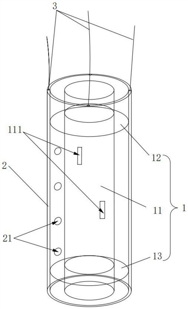
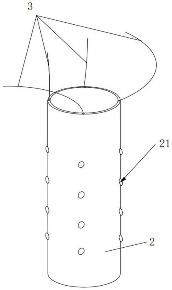
The invention belongs to the technical field of geotechnical engineering grouting, and discloses a grouting structure for a sleeve valve pipe. The grouting structure comprises a grouting assembly and a sleeve pipe, wherein the grouting assembly comprises a grouting pipe head, a first elastic ring and a second elastic ring, the first elastic ring and the second elastic ring are arranged at the two ends of the grouting pipe head in a sleeving mode correspondingly, and a grouting hole is formed in the grouting pipe head and located between the first elastic ring and the second elastic ring; the sleeve pipe is movably arranged outside the first elastic ring and the second elastic ring which are both subjected to elastic deformation in a sleeving mode, the sleeve pipe is configured to be capable of being inserted into the sleeve valve pipe, and the outer diameter of the sleeve pipe is smaller than the inner diameter of the sleeve valve pipe; and a gap is formed between the sleeve pipe and the sleeve valve pipe, so that the grouting pipe head can be conveniently inserted into or pulled out of the sleeve valve pipe. The sleeve pipe can be pulled away from the position between the sleeve valve pipe and the grouting pipe head, so that the first elastic ring and the second elastic ring abut against the inner wall of the sleeve valve pipe; and the sleeve pipe can further be inserted between the sleeve valve pipe and the grouting pipe head, so that the first elastic ring and the second elastic ring abut against the inner wall of the sleeve pipe.

Description

technical field [0001] The invention relates to the technical field of geotechnical engineering grouting, in particular to a grouting structure for sleeve valve pipes. Background technique [0002] The sleeve valve pipe grouting method is an economical and practical grouting process. The biggest advantage of this method is its strong adaptability and convenience. And other projects are widely used. [0003] At present, the main process of grouting the sleeve valve pipe is: after the hole is drilled with a drilling machine, the casing material is sent into the hole by the drilling machine, and then the sleeve valve pipe is lowered into the casing material. A through hole is arranged on the outer wall of the sleeve valve tube and is blocked with a rubber stopper. When grouting, insert the grouting pipe head with sealing rubber plugs at both ends into the sleeve valve pipe, under the pressure of the grout, the rubber plug opens, and the grout enters the formation from the thr...

Claims


Application Information

Patent Timeline
IPC IPC(8): E02D15/04E02D3/12
CPCE02D15/04E02D3/12
Inventor 孙九春奚晓广王瑞
Owner TENGDA CONSTR GROUP CORP
Learn More