
Closestool flushing system, pressurizing device and pressure relief structure of pressurizing device

A technology of pressure relief structure and pressurization device, which is applied to water supply devices, flushing toilets, and sanitary equipment for toilets. Simple, simple design, reliable opening and closing control effect

Inactive Publication Date: 2021-12-24
GULI (XIAMEN) TECH CO LTD
View PDF0 Cites 0 Cited by
  • Summary
  • Abstract
  • Description
  • Claims
  • Application Information

AI Technical Summary

Problems solved by technology

However, the structure of the electromagnetic valve is complicated and the cost is high.
In order to solve the problem of complex structure and high cost of electromagnetic valves, some pressure relief structures use Y-shaped sealing rings to realize the opening and closing of pressure relief channels. Y-shaped sealing rings are prone to failure, which can easily lead to poor sealing.

Method used


Image

  • Closestool flushing system, pressurizing device and pressure relief structure of pressurizing device
  • Closestool flushing system, pressurizing device and pressure relief structure of pressurizing device
  • Closestool flushing system, pressurizing device and pressure relief structure of pressurizing device

Examples


Embodiment Construction

[0034] In order to make the technical problems, technical solutions and beneficial effects to be solved by the present invention clearer and clearer, the present invention will be further described in detail below in conjunction with the accompanying drawings and embodiments. It should be understood that the specific embodiments described here are only used to explain the present invention, not to limit the present invention.

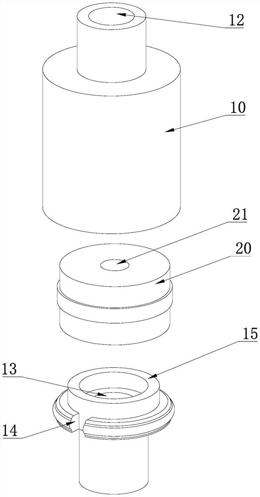
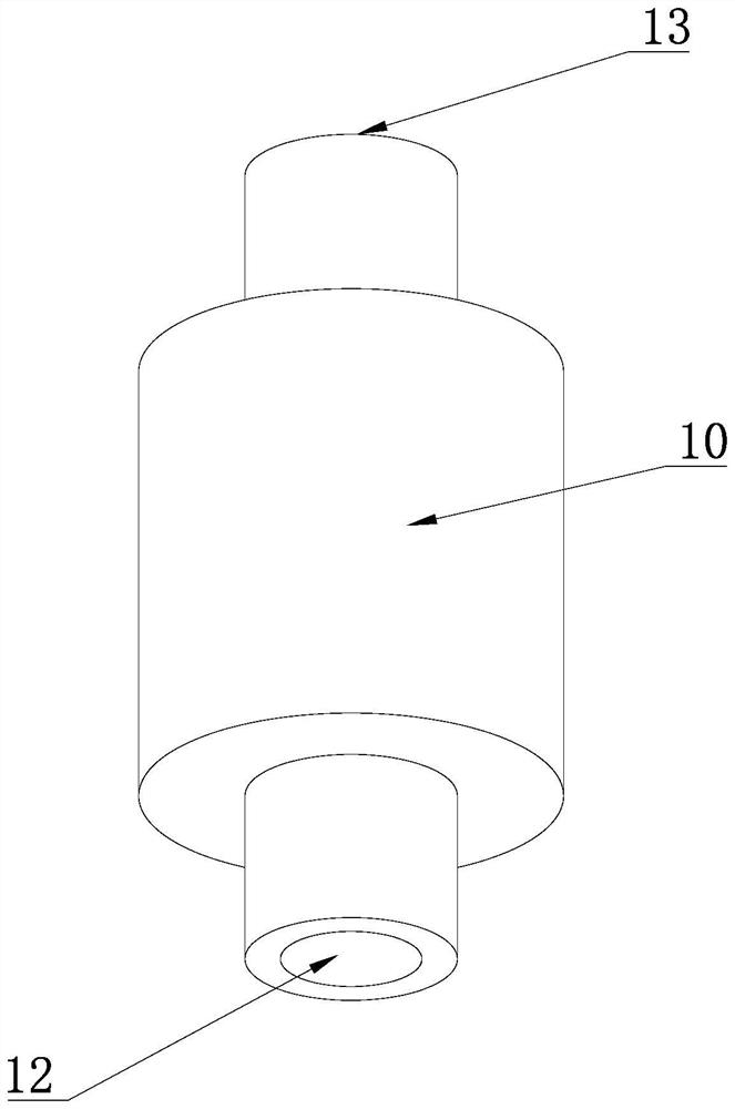
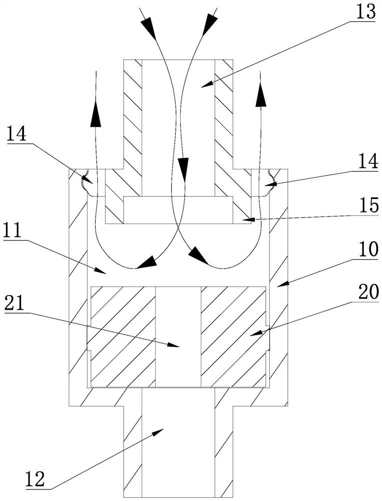
[0035] Please check Figure 1 to Figure 4 , a pressure relief structure of a pressurizing device according to an embodiment of the present invention, comprising:

[0036] The pressure relief body 10 has a pressure relief chamber 11, an inlet passage 12, an outlet passage 13 and a pressure relief passage 14. The inlet passage 12, the outlet passage 13 and the pressure relief passage 14 are respectively connected to the pressure relief chamber 11, and the inlet passage 12 is connected to the pressure relief chamber 11. The source 1 is connected, and the ...


PUM


Abstract

The invention discloses a pressure relief structure of a pressurizing device, which comprises a pressure relief body and a movable part; the pressure relief body is provided with a pressure relief cavity, a pressure relief channel, an inlet channel and an outlet channel communicated with a pressurizing cavity of the pressurizing device, and the inlet channel, the outlet channel and the pressure relief channel are respectively communicated with the pressure relief cavity; the movable part is provided with a through-flow channel, fluid in the inlet channel flows to the outlet channel through the through-flow channel, and the through-flow sectional area of the through-flow channel is smaller than that of the inlet channel; after the pressure source inputs pressure fluid into the inlet channel, the movable part moves towards one side of the outlet channel to a second position under the action of the pressure difference between the two sides of the movable part so as to close the pressure relief channel; after the pressure source stops inputting the pressure fluid into the inlet channel, the movable part moves to the first position towards one side of the inlet channel under the action of reset force so as to open the pressure relief channel. The pressure relief structure is simple, reliable in function and low in cost. The invention further discloses a pressurizing device with the pressure relief structure and a closestool flushing system.

Description

technical field [0001] The invention relates to a pressure relief structure, a pressurizing device with the pressure relief structure, and a toilet flushing system with the pressurization device. Background technique [0002] Among the existing fluid pressurizing devices, the piston-type pressurizing device is a relatively common structure, which usually includes a housing and a piston, the housing has an inner cavity, and the piston can be reciprocally slidably arranged in the housing and the inner cavity of the housing Divided into a first chamber and a second chamber, the first chamber is in communication with the fluid source, the second chamber is in fluid communication with the outer part, and the fluid source provides pressure fluid to the first chamber to drive the piston to compress the second chamber under the action of the pressure fluid The fluid inside flows to the outer part. During the piston reset process, the fluid in the first chamber needs to be released ...

Claims


Application Information

Patent Timeline
Patent Type & Authority Applications(China)
IPC IPC(8): E03D9/16E03D11/18E03D11/13
CPCE03D9/16E03D11/18E03D11/13
Inventor 陈雪瑜
Owner GULI (XIAMEN) TECH CO LTD
Learn More