LED lamp for outdoor lighting

A technology for LED lights and outdoor lighting, applied in the field of lighting, can solve the problems affecting the lighting effect of the LED lights in the lampshade and the adhesion of dust and impurities to the lampshade, and achieve the effect of saving the use cost and efficient heat dissipation.

Inactive Publication Date: 2021-12-24
佛山市凯迅光健康工程技术研究院
View PDF0 Cites 1 Cited by
  • Summary
  • Abstract
  • Description
  • Claims
  • Application Information

AI Technical Summary

Problems solved by technology

[0005] In order to make up for the deficiencies of the existing technology, when the LED lamp for outdoor lighting is used for a long time, some dust and impurities will adhere to the bottom surface of the lampshade. If it is not cleaned in time, as the dust and impurities gradually accumulate, it will affect the LED lamp in the lampshade. The problem of lighting effects, the present invention provides an LED lamp for outdoor lighting

Method used


Image

  • LED lamp for outdoor lighting
  • LED lamp for outdoor lighting
  • LED lamp for outdoor lighting

Examples


Embodiment 1

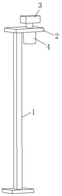
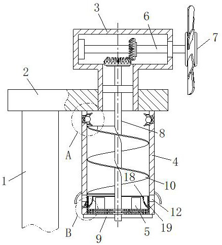
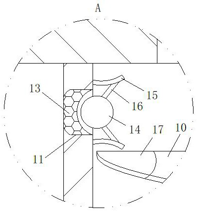
[0028] see Figure 1-4 As shown, an LED lamp for outdoor lighting according to the present invention includes a lamp stand 1; a support plate 2 is connected to the top of the light stand 1, and a power chamber 3 is connected to the top of the support plate 2, and the power chamber 3 A lampshade 4 is connected to the bottom surface of the support plate 2 corresponding to the bottom end, and the inner bottom end of the lampshade 4 is provided with a lamp body 5, and the inside of the power chamber 3 is connected to a No. The free end of the second rotating rod 8 is connected with a power fan 7, and the middle part of the first rotating rod 6 is connected with a second rotating rod 8 through a bevel gear pair. The free end of the second rotating rod 8 is located at the outer end of the bottom surface of the lampshade 4 and is connected with The scraper 9 that is in contact with the bottom surface of the lampshade 4; when the LED lamp for outdoor lighting in the prior art is used ...

Embodiment 2

[0036] see Figure 5 As shown, a water-absorbing layer 28 is laid on the bottom surface of the lampshade 4 corresponding to the inside of the limiting sleeve 18, and the No. 1 water outlet holes 26 at the upper and lower ends of the cavity are respectively filled with water-absorbing blocks 29, and the water-absorbing layers at the bottom of the cavity Inside the block 29 there is a squeeze ball 30, the bottom of the squeeze ball 30 is connected to the side wall of the No. 1 water outlet hole 26 through an elastic strip 31, and the squeeze ball 30 can drive the water-absorbing block 29 to protrude to the No. 1 water outlet The top of the hole 26, and the bottom end of No. 1 water outlet hole 26 at the extrusion ball 30 is connected with a blocking net 32, and the inside of the No. 2 water outlet hole 27 is filled with a connecting block 33 of water-absorbing material; the water-absorbing layer 28 can limit The rainwater condensed inside the cover 18 is effectively absorbed, an...


PUM


Abstract

The invention relates to the technical field of lighting lamps, and in particular, relates to an LED lamp for outdoor lighting, wherein the LED lamp comprises a lamp holder; a supporting plate is connected to the top end of the lamp holder, a power chamber is connected to the top end of the supporting plate, a lampshade is connected to the bottom face, corresponding to the bottom end of the power chamber, of the supporting plate, and a lamp body is arranged at the bottom end in the lampshade; a first rotating rod is rotationally connected to the interior of the power chamber; a power fan is connected to the free end of the first rotating rod; and the middle of the first rotating rod is connected with a second rotating rod through a bevel gear pair, and the free end of the second rotating rod is located at the outer end of the bottom face of the lampshade and connected with a scraping plate. The power fan can be used for driving the scraping plate to scrape and clean dust and impurities attached to the bottom face of the lampshade; meanwhile, the lampshade is cleaned in the mode that natural wind energy is converted into kinetic energy, an electric sweeping structure does not need to be arranged on the lampshade any more, the use cost of the illuminating lamp is saved, and the LED illuminating lamp is more energy-saving and environmentally friendly.

Description

technical field [0001] The invention relates to the technical field of lighting lamps, in particular to an LED lamp for outdoor lighting. Background technique [0002] Outdoor LED lighting is mainly floodlights, also known as spotlights. Usually, it can be aimed at any direction and has a structure that is not affected by weather conditions. It is mainly used in large-scale mines, construction sites, etc.; A light lamp generally includes a lamp housing, a light-emitting circuit board arranged in the lamp housing, a plurality of LED light sources connected to the light-emitting circuit board, a switch, a power supply, a bracket, and the like. Wherein, the front of the lamp housing is often provided with a light-transmitting hole. When the power is turned on, the light emitted by the LED light source is irradiated from the front of the lamp housing to form a lighting area. [0003] However, when the LED lamp for outdoor lighting in the prior art is used for a long time, some ...

Claims


Application Information

Patent Timeline
Patent Type & Authority Applications(China)
IPC IPC(8): F21S8/08F21V29/67F21V29/83F21V33/00B01D46/30B08B1/00B08B3/00F21W131/10F21Y115/10
CPCF21S8/086F21V33/00F21V29/67F21V29/83B08B1/005B08B3/00B01D46/30F21W2131/10F21Y2115/10Y02B20/72
Inventor 梁明
Owner 佛山市凯迅光健康工程技术研究院
Why Eureka
Try Eureka