Engineering cost field surveying and mapping equipment
A project cost and on-site technology, applied in the field of project cost on-site surveying and mapping equipment, can solve the problems of insufficient height adjustment stability, inconvenient manual operation, inconvenience to carry, etc., and achieve the effect of improving practicability, easy operation and improving stability.
- Summary
- Abstract
- Description
- Claims
- Application Information
AI Technical Summary
Problems solved by technology
Method used
Image
Examples
Embodiment 1
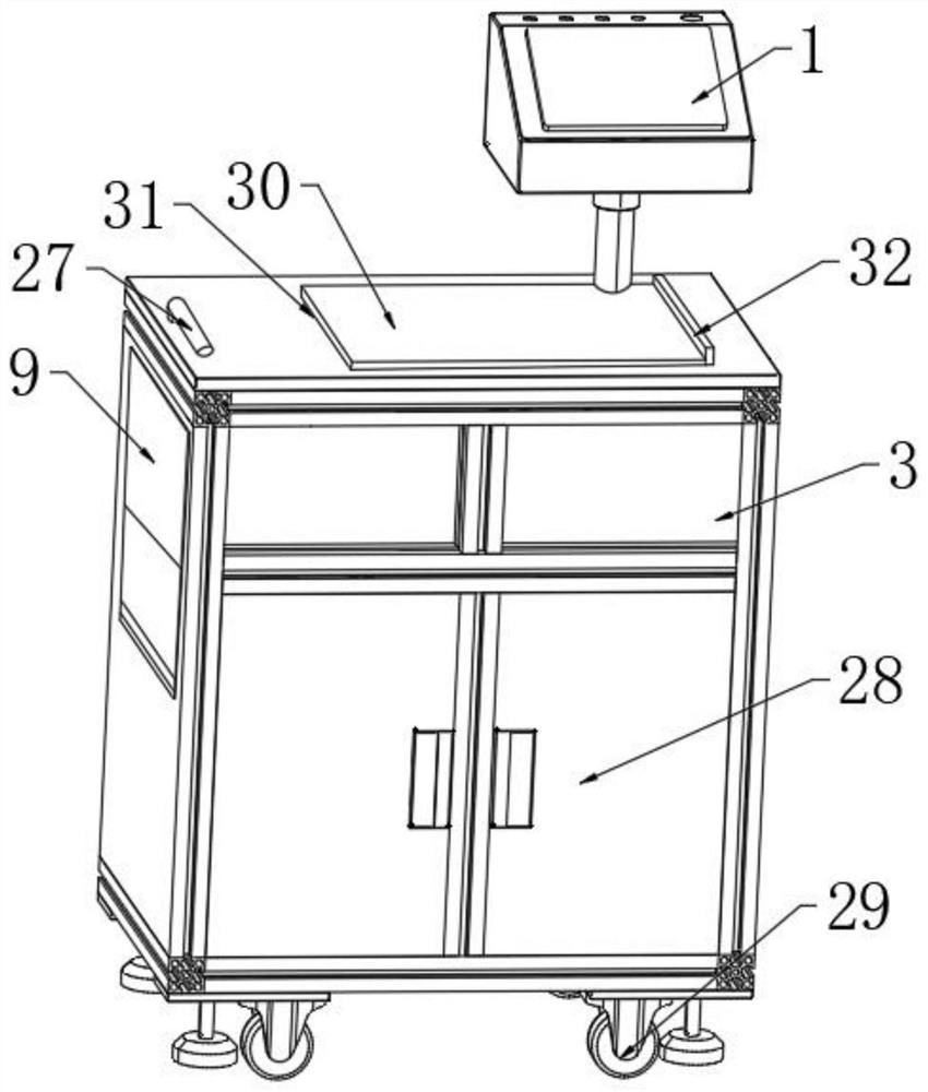
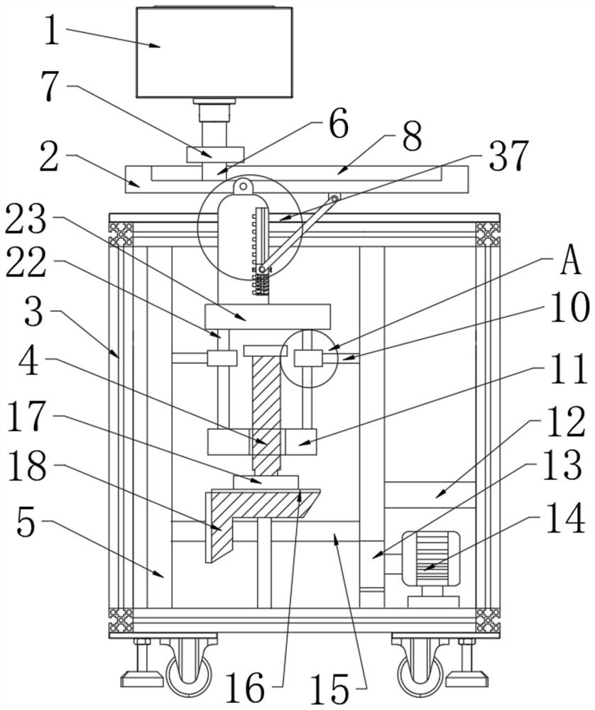
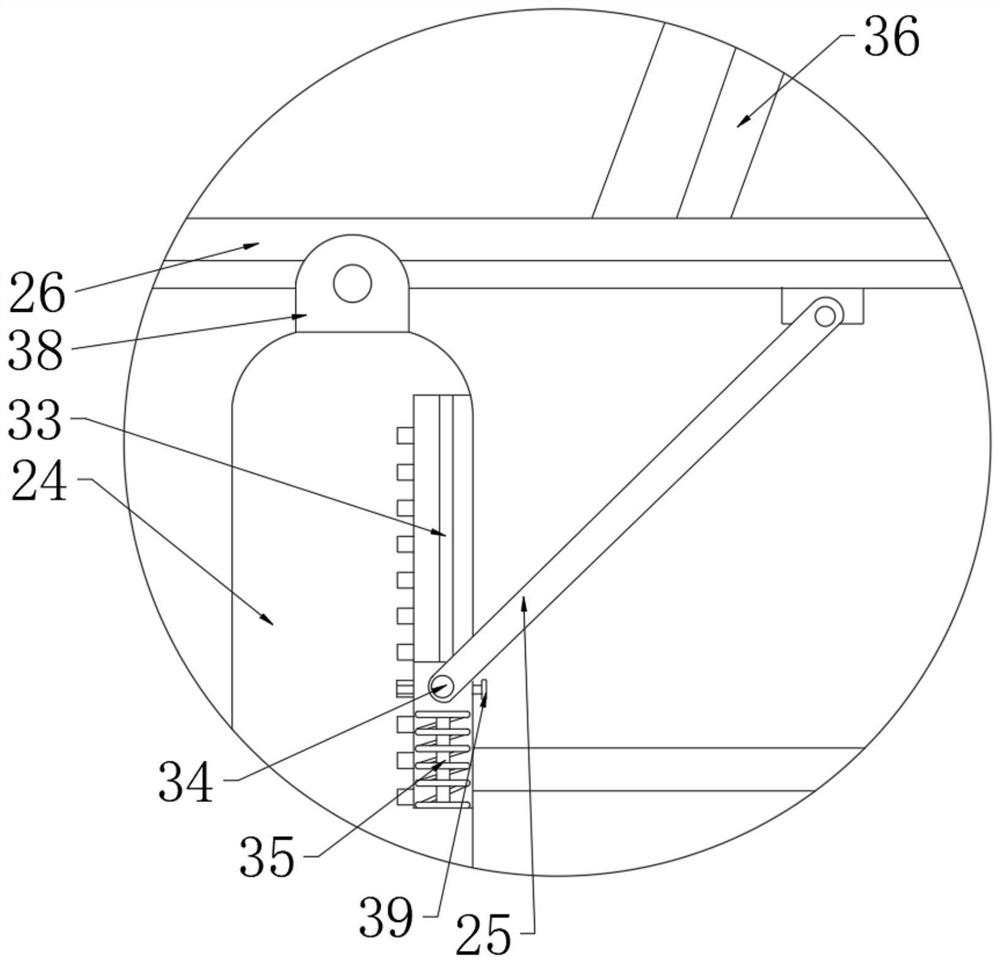
[0030] Such as Figure 1-8 As shown, an engineering cost on-site surveying and mapping equipment according to an embodiment of the present invention is composed of a surveying and mapping device body 1 shading device 9 supporting device 37 .
[0031] Wherein, although the existing engineering cost on-site surveying and mapping equipment can set up a certain height, the stability in the process of height adjustment is not high enough, and it is not convenient for manual operation. A support device 37 is provided including the first partition 5, The transmission rod 15, the first bevel gear 18, the second bevel gear 16 and the support plate 2, the inside of the box body 3 is vertically welded with a first partition 5 near the center, and the first partition 5 is provided with two , the first dividing plate 5 is symmetrical about the vertical center line of the box body 3, a transmission rod 15 is horizontally arranged between the first dividing plates 5, and a first bevel gear 1...
Embodiment 2
[0041] On the basis of Example 1, please refer to figure 1 One end of the top of the box body 3 is fixedly connected with a handle 27, the front side surface of the box body 3 is provided with a door leaf 28, the bottom of the box body 3 is connected with the universal wheel 29 bolts, and the top of the box body 3 is connected with the placement plate 30 in rotation, and placed One side of the board 30 is integrated with the clamping rod 31 , and the other side of the board 30 is provided with a box cover 32 .
[0042] By adopting the above-mentioned technical scheme, a handle 27 is fixedly connected to one end of the top of the box body 3, and the handle 27 can be conveniently pushed and transported. The wheel 29 is bolted, and the universal wheel 29 is set to improve the portability of the equipment. At the same time, it does not need manpower to lift, which saves manpower. The side is provided with box cover 32.
Embodiment 3
[0044] On the basis of Example 1, please refer to figure 1 and figure 2 A connecting rod 10 is welded horizontally between the first partitions 5, and the end of the connecting rod 10 away from the first partition 5 is welded with a limit block 20, and the inner surface wall of the limit block 20 is provided with a groove 19, and the groove 19 is along the There are four limiting blocks 20 in the circumferential direction, and rollers 21 are arranged inside the groove 19 via a rotating shaft.
[0045] By adopting the above technical solution, the first partition 5 divides the inner space of the box body 3 on the one hand, and also supports the transmission rod 15 on the other hand, and the connecting rod 10 is welded horizontally between the first partitions 5 A limit block 20 is welded to the end of the connecting rod 10 away from the first partition 5 , and the limit block 20 limits the moving position of the support rod 22 .
PUM
 Abstract
Description
Claims
Application Information
 - R&D Engineer
- R&D Manager
- IP Professional
- Industry Leading Data Capabilities
- Powerful AI technology
- Patent DNA Extraction
Browse by: Latest US Patents, China's latest patents, Technical Efficacy Thesaurus, Application Domain, Technology Topic, Popular Technical Reports.
© 2024 PatSnap. All rights reserved.Legal|Privacy policy|Modern Slavery Act Transparency Statement|Sitemap|About US| Contact US: help@patsnap.com


