
Bearing fault diagnosis method, system, device and terminal

A fault diagnosis and bearing technology, which is applied in equipment and terminals, bearing fault diagnosis methods, and system fields, can solve problems such as the lack of DNN network to provide architectural details, the depth of DNN models, and the lack of clear explanations for the gradual model construction process.

Pending Publication Date: 2021-12-24
XIDIAN UNIV
View PDF0 Cites 7 Cited by
  • Summary
  • Abstract
  • Description
  • Claims
  • Application Information

AI Technical Summary

Problems solved by technology

[0005] (1) In the existing bearing fault diagnosis methods, no architectural details are provided for the proposed DNN network
[0006] (2) In the existing bearing fault diagnosis methods, only training accuracy (not test accuracy) is provided, and no feasible architecture is provided for the proposed network, which makes it difficult to reproduce
[0007] (3) In the existing technical solutions that focus on both CNN and long-short-term memory network LSTM for bearing fault diagnosis, the step-by-step construction process of the model has not been clearly explained
[0009] (1) Many DNN models have a large depth and complex structure
[0010] (2) When training and testing the model, the test accuracy is generally smaller than the training accuracy. Given the training accuracy, a higher accuracy rate can be obtained, but it cannot explain the excellence of the model method better than the test accuracy.
[0011] (3) Sometimes the construction model is the final result obtained through continuous adjustment of result feedback, and it is difficult to explain the construction process

Method used


Image

  • Bearing fault diagnosis method, system, device and terminal
  • Bearing fault diagnosis method, system, device and terminal
  • Bearing fault diagnosis method, system, device and terminal

Examples


Embodiment Construction

[0156] In order to make the object, technical solution and advantages of the present invention more clear, the present invention will be further described in detail below in conjunction with the examples. It should be understood that the specific embodiments described here are only used to explain the present invention, not to limit the present invention.

[0157] Aiming at the problems existing in the prior art, the present invention provides a bearing fault diagnosis method, system, equipment and terminal. The present invention will be described in detail below with reference to the accompanying drawings.

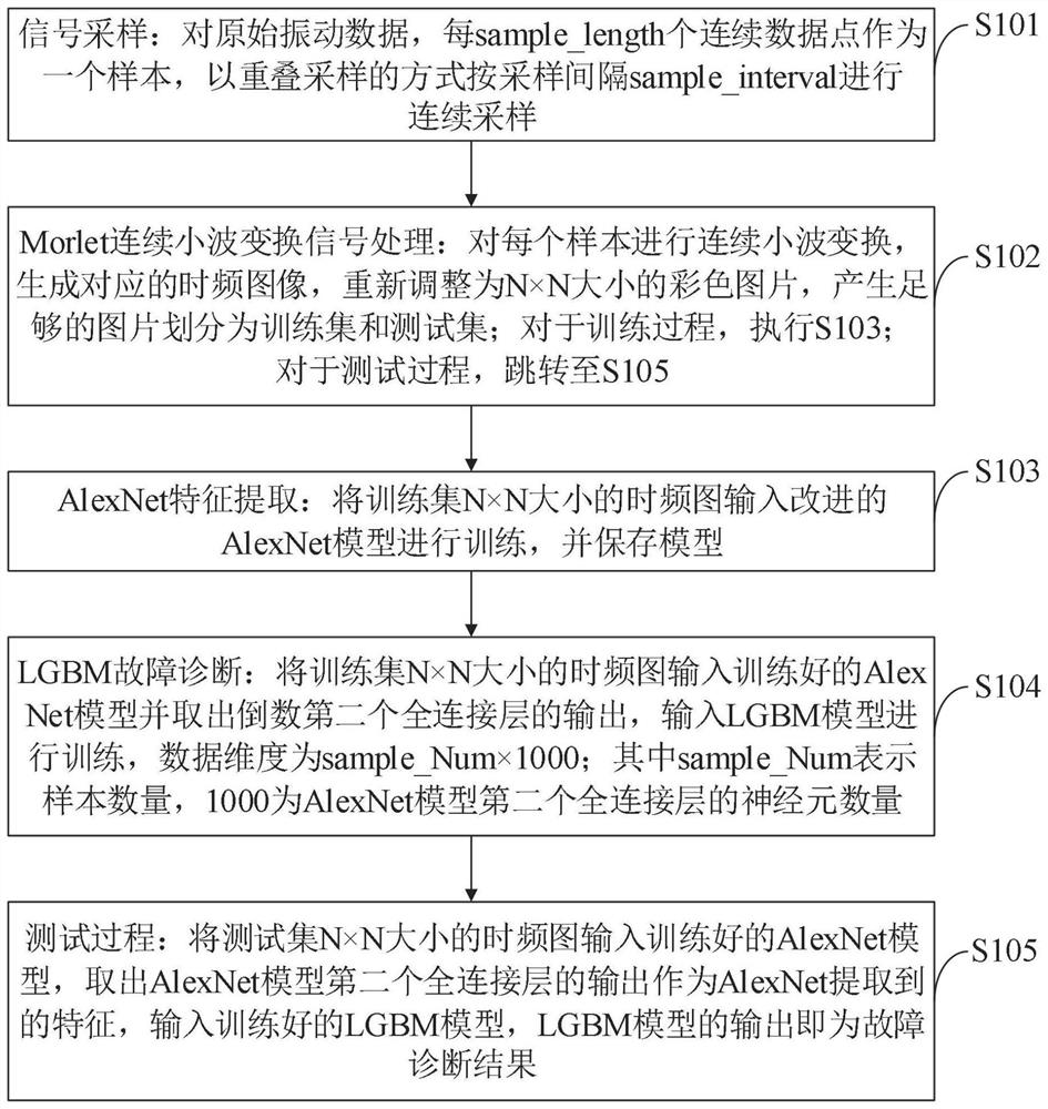
[0158] Such as figure 1 As shown, the bearing fault diagnosis method provided by the embodiment of the present invention includes the following steps:

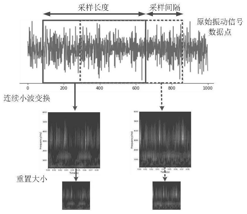
[0159] S101, signal sampling: for the original vibration data, every sample_length continuous data points are taken as a sample, and continuous sampling is performed according to the sampling interval sample_interval in ...


PUM


Abstract

The invention belongs to the technical field of bearing fault diagnosis, and discloses a bearing fault diagnosis method, system, device and terminal, and the method comprises the steps: extracting the time-frequency features of an original vibration signal of a bearing through continuous wavelet transform, and converting the time-frequency features into a 32 * 32 pixel two-dimensional image; using an improved AlexNet model to carry out fault feature extraction on the time-frequency spectrogram; for fault diagnosis classification, selecting optimal model parameters through an LGBM classification algorithm and Bayesian optimization. The bearing fault diagnosis method provided by the invention has optimal fault diagnosis accuracy. Through experimental comparison, compared with other seven methods, the method provided by the invention has the highest accuracy rate of 99.712%, the prediction time consumption of 1.47 seconds for 1800 samples is also at the same order of magnitude as the time consumption of other models, the variance of the accuracy rates of five times of prediction is only 0.063, and the method provided by the invention is more stable than other six methods and has optimal comprehensive performance.

Description

technical field [0001] The invention belongs to the technical field of bearing fault diagnosis, and in particular relates to a bearing fault diagnosis method, system, equipment and terminal. Background technique [0002] At present, effective fault diagnosis of mechanical equipment can reduce huge economic losses in industrial production. In recent years, the application of machine learning or deep learning technology has greatly increased. In addition, the use of advanced measurement technology has enabled a large amount of data to be collected in industrial environments. . In the context of big data, machine learning and deep learning fault diagnosis algorithm models have shown excellent results, such as deep neural network (Deep Neural Network, DNN), CNN, recurrent neural network, etc. [0003] Currently, autoencoders and convolutional neural networks are relatively common in deep learning fault diagnosis models. Lei et al. proposed a deep neural network for fault diagn...

Claims


Application Information

Patent Timeline
IPC IPC(8): G01M13/045G06N3/04G06N3/08
CPCG01M13/045G06N3/04G06N3/08
Inventor 刘立芳张梓锐和伟辉李飞龙齐小刚
Owner XIDIAN UNIV
Learn More