[0038] The following detailed description will be further described below with reference to the accompanying drawings and examples. It will be appreciated that the specific embodiments described herein are only used to explain the relevant invention, not the limitation of the invention. It will also be otherwise that only the portion related to the invention is shown in the drawings.
[0039] It should be noted that the features of the present application and the features in the embodiments in the present application can be combined with each other in the case of an unable conflict. The present application will be described in detail below with reference to the accompanying drawings.
[0040] Electronic devices include, but are not limited to, computing devices such as laptop, computer monitors, tablets, tablets, cellular phones, media players, or other handheld or portable electronic devices, smaller devices, such as a watch Equipment, hanging equipment, headphones or handset devices, embedded glasses or other devices in devices that wear on the user's head, or other wearable or micro-devices, computer displays, computer displays, game devices , Navigation devices, embedded systems, such as electronic devices having a display, mounted in information kiosks or vehicles, and implement two or more of the functions of these devices, or other electronic devices.
[0041] The outer casing may be called a housing or hood, which can be combined by plastic, glass, ceramic, fiber composite, metal (eg, stainless steel, aluminum, etc.), other suitable materials or these materials. form. The outer casing can be formed using an integrated configuration, and some or all of the outer casings are processed or molded into a single structure, or a plurality of structures (e.g., inner frame structures, one or the surface of the outer housing can be used. A variety of structures, etc.) formation.
[0042] The frame 1, which may be a separate structure of the outer casing or an integral structure at the boundary position of the outer casing, and the structure formed in the housing may also include a bracket, a rear cover, and the like.
[0043] The antenna can be used for processing wireless communication in the following frequency range: low communication band from 700 to 960 MHz, from 1710 to 2170 MHz, and high band from 2300 to 2700 MHz, or at 700 MHz and 2700 MHz Other communication bands, or other suitable frequencies. It is also possible to use 2.4 GHz and 5GHz bands in WiFi (IEEE 802.11) and can process 2.4 GHz Bluetooth communication bands. It is also possible to include satellite navigation system circuitry, such as a Global Positioning System (GPS) receiver circuit, for receiving a GPS signal of 1575 MHz or for processing other satellite positioning data.
[0044] A plurality of antennas may be included on the electronic device, with at least one antenna as a telescopic antenna provided herein.
[0045] The type of antenna can be a ring antenna structure, a patch antenna structure, an inverted antenna structure, a slot antenna structure, a planar inverted antenna structure, a spiral antenna structure, or a mixing of several structures.
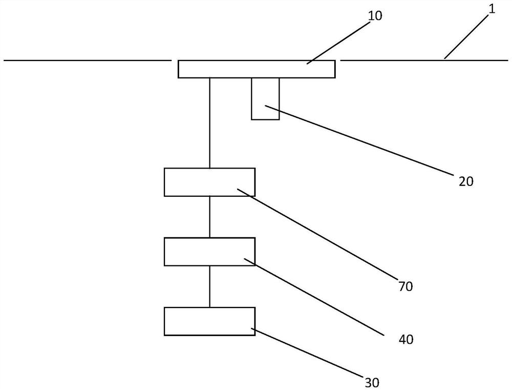
[0046] Please see figure 1 This application provides a telescopic antenna, including:
[0047] Antenna radiator 10.
[0048] The first drive mechanism 20 is used to drive the antenna radiator 10 in line with a straight line between the first position and the second position, the first position being a position that is flat to the frame 1 of the electronic device, the second position It is an external position of the electronic device border 1.
[0049] The radio frequency transceiver 10 is used to transmit and receive radio frequency signals by the antenna radiator 10.
[0050] The impedance matching member 40 includes a plurality of matching circuits, the impedance matching member 40 for connecting the antenna radiator 10 and the radio frequency based on the position selectable matching circuit based on the position of the antenna radiator 10. Transceiver 10.
[0051] In the first position, the antenna is built in the first position, and the first position is a position that is flat to the frame 1 of the electronic device, which can be used as the external trifice of the mobile terminal, thereby playing a beautification At the same time, do not add additional antenna, saving the space inside the mobile terminal to meet the needs of mobile terminal miniaturization.
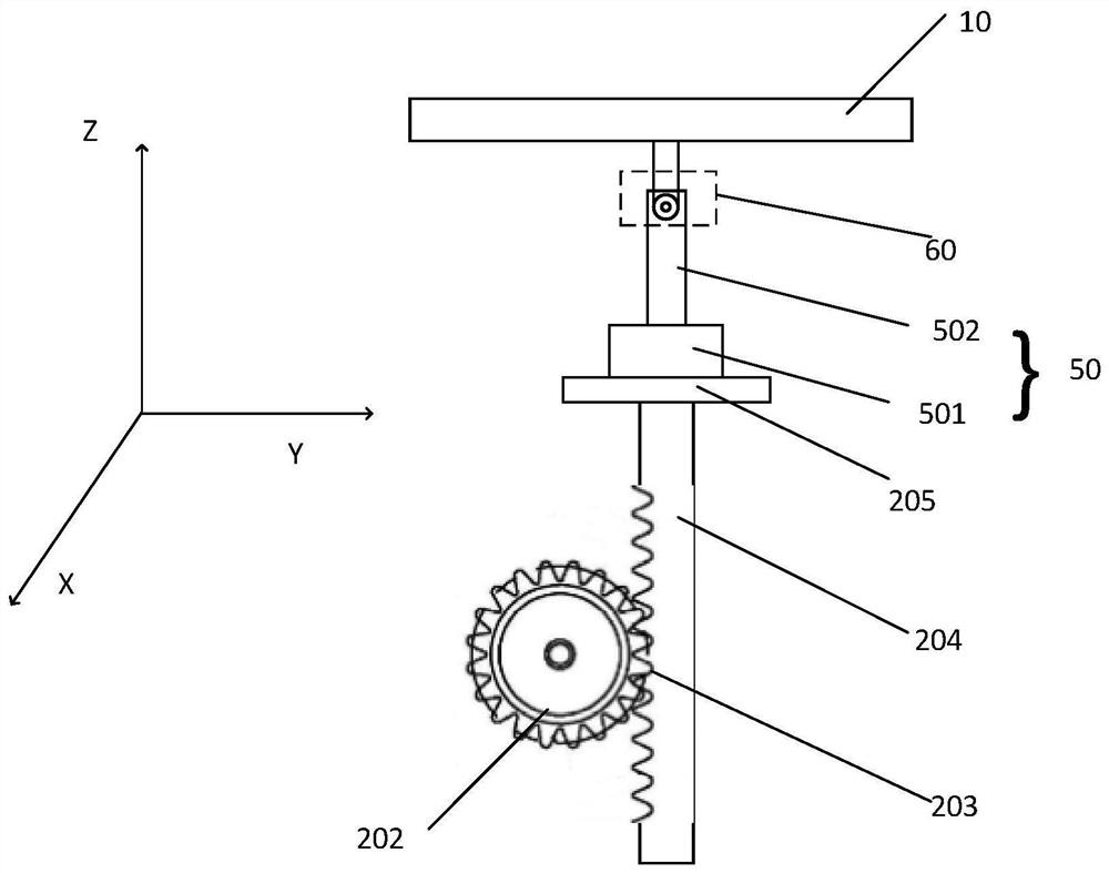
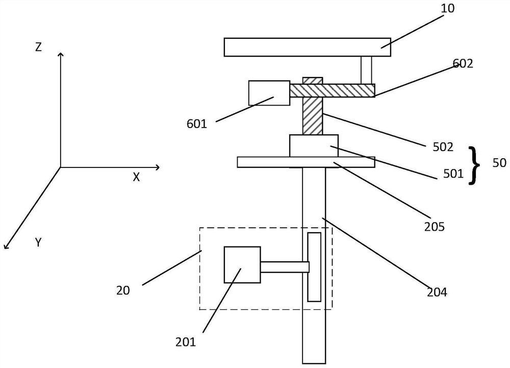
[0052] Such as figure 2 , image 3 As shown, in one embodiment of the present application, the telescopic antenna further includes:
[0053]The second drive mechanism 50 is configured to drive the antenna radiator 10 in the first direction, the first direction to the first position pointing vertically in the direction of the second position; and / or
[0054] The third drive mechanism 60 is used to drive the antenna radiator 10 in the second direction, the second direction to the first direction vertical.
[0055] In the present application embodiment, the plane of the antenna radiator 10 is the XOY plane, and the direction of movement of the telescopic antenna is the Z-axis direction, defining the first direction is located in the XOY plane, rotation in the Z-axis, and therefore, The two drive mechanism 50 drives the antenna radiator 10 to rotate about Z axis; defines the second direction at the YOZ plane, rotation in the X-axis, so that the third drive mechanism 60 drives the antenna radiator 10 to rotate about the X-axis; or define The second direction is the Xoz plane, rotation in the Y-axis, so the third drive mechanism 60 drives the antenna radiator 10 to rotate about the Y axis. In some embodiments, the first direction and the second direction can be interchangeable.
[0056] In the specific setting, the first drive mechanism 20, the second drive mechanism 50, the third drive mechanism 60 can be implemented in a variety of mechanical manner when moving and rotating. In the present application embodiment, the first drive mechanism 20, the second drive mechanism 50, and the third drive mechanism 60 are exemplarily described.
[0057] The first drive mechanism 20 includes a first motor 201, a gear 202 coupled to the first motor 201, a rack 203 that is fitted with the gear 202. The gear 202 is rotated by the first motor 201, and the rack 203 is mounted with the rack 203 to move in the Z-axis direction.
[0058] The second drive mechanism 50 includes a second motor 501, a rotating shaft 502 connected to the second motor 501, rotating the shaft 502 by the second motor 501, and achieves the rotating shaft 502 around the Z-axis.
[0059] The third drive mechanism 60 includes a third motor 601, a connecting shaft 602 connected to the third motor 601, rotating the connecting shaft 602 by the third motor 601, and achieves the connecting shaft 602 to rotate about the X-axis.
[0060] When the first motor 201 is provided, the first motor 201 is provided inside the electronic device, and the rack is disposed on the moving shaft 204 connected to the antenna radiator 10, and the movement shaft 204 is moved up and down by the gear 202, and realizes the antenna. Telescopic function.
[0061] The second motor 501 is disposed on the base 205 on the moving shaft 204, and the third motor 601 is disposed on the rotating shaft 502, and the direction of the connecting shaft 602 of the third motor 601 is perpendicular to the direction of the rotating shaft 502. In one embodiment of the present application, the connecting shaft 602 is rotatable between the shaft 502. Wherein, the direction of the rotating shaft 502 is in the direction of the connecting shaft 602 in the direction of the Z-axis direction.
[0062] It should be noted that the first motor 201 drives the second motor 501 and the third motor 601 to move with the moving shaft 204 with the moving shaft 204, and the second motor 501 rotates together. Of course, in other embodiments, other driving mechanisms can also be included. Different setting methods can be made without violating the concept of the present invention.
[0063] Additionally, the telescopic antenna further includes a feed connector 70 that feeds the antenna radiator 10 by direct feed or coupling feed.
[0064] In the present application, the electromagnetic energy emitted by the radio frequency transceiver member 30 achieves the radio frequency function of the antenna by matching the impedance member and the feed connector to the antenna radiator 10.
[0065] In one embodiment of the present application, both the position, area, and shape of the feed connector can be selected according to the design of the electronic device.
[0066] The feed connector can be a metal sheet or a surface metallized component during direct feed. Components using metal sheets or surface metallization are low as feeding parts, and have good coupling feed properties. Wherein, the components of the surface metal ring may be a metallization component formed on a PCB plate or ceramic sheet.
[0067] When the feed connector is fed by a coupling manner, the feed connector can be achieved between the feed docking point 11 of the antenna or by filling the feed medium in the gap, wherein the feed medium can include a metal medium or Non-metallic media.
[0068] In the present application embodiment, the impedance matching member 40 includes a first matching circuit 42 and a second matching circuit 43 having an antenna output impedance at the first position at the first position; the first matching circuit 42; The second matching circuit 43 corresponds to the antenna output impedance at the second position at the second position.
[0069] Wherein, when the first matching circuit 42 is used in the antenna radiator 10, i.e., an antenna built-in state, the first matching circuit 42 is used to match an antenna output impedance to match its operating frequency band. When the second matching circuit 43 is used in the antenna radiator 10, that is, when the antenna is in an external state, the second matching circuit 43 is used to match the antenna output impedance to match its operating frequency band. Since the antenna radiator 10 is moved upward, the distance between the antenna radiator 10 and the radio frequency transmitting and receiving member 30 generates a bias when it is set thereof. By setting the adjustable second matching circuit 43, according to the position thereof, the output impedance of the antenna is corrected, so that the problem with the bias is improved, and the antenna radiation performance is improved.
[0070] In one embodiment in this application, the impedance matching member 40 includes a switching switch 41. Such as Figure 4 As shown, in the application, two matching circuits are included in the impedance matching member 40, and therefore, the switching switch 41 can select a single knife double throw switch. The output terminal of the switching switch 41 is connected to the antenna radiator 10, and the first input of the switching switch 41 is connected to the first matching circuit 42, the second input of the switching switch 41 and the The second matching circuit 43 is connected.
[0071] In other embodiments, the type of switching switch 41 is provided with the number of matching paths, and the impedance matching member 40 may also include three matching circuits, the corresponding switching switch 41 can choose a single knife three-throw switch, including more, You can choose MUX (multiplexing), and the like.
[0072] Wherein, the first matching circuit 42 and the second matching circuit 43 are at least one of a resistance matching circuit, a capacitance matching circuit, or an inductive matching circuit.
[0073] Increased small resistance or inductance is advantageous for the low frequency resonance of the antenna, increasing capacitance facilitates low frequency resonant polarization, increased inductance, and capacitance combinations facilitates adjusting the designated resonance.
[0074] In the present application embodiment, when the antenna is converted into an external state, it is equivalent to the antenna in a pure empty external environment, and the radiation environment of the antenna is improved, and the radiation performance of the antenna is improved, but for built-in and external When the same operating frequency segment, due to the change in the radiation environment, the influence problem under the same operating frequency band is produced. Thus, in the present application embodiment, the effect of resonant opticization is generated by setting the first matching circuit 42 and the second matching circuit 43 for matching an antenna different working environment, and the antenna radiation performance is improved.
[0075] It should be noted that in the present application embodiment, the second matching circuit 43 may also include several matching sub-circuit 402 for matching different adjustment parameters of the antenna.
[0076] Exemplarily, the second matching circuit 43 includes three matching sub-circuit 402. Such as Figure 5 As shown, each matching sub-circuit 402 includes a tandem device or a parallel device, wherein the series device or parallel device can be a capacitor or inductor for impedance matching of the antenna radiator 10. The parallel device is not limited to the order of the series devices; different matching sub-circuit 402 has different impedance values. Depending on the location, you can choose to access different matching sub-circuits 402.
[0077] The second matching circuit 43 includes a control switch 401 for switching the matching sub-circuit 402 in the second matching circuit 43. The type of control switch 401 is set as the number of matches of sub-circuit 402, for example, the second matching circuit 43 includes three matching sub-circuit 402, and the corresponding control switch 401 can select a single-knife three-throw switch, and when including more, Select MUX (Multi-Switch) and so on.
[0078] It is also necessary to explain that the electronic device in the present application embodiment includes a plurality of antennas, and the frequency band of different antennas is different. Thus, for different telescopic antennas, where different matching circuits and matching sub-circuit 402 can have different impedance values to adapt to the antenna of different frequency bands to match tuning.
[0079] In the present application embodiment, the electronic device includes a motherboard 80, such as a planar printed circuit board (PCB, PrintedCircuit Board). The radio frequency transmitting and receiving section 30, the impedance matching circuit is provided on the motherboard 80, and the feeding point 11 is provided on the antenna radiator 10, and the feed point 11 is connected to the antenna shrapnel on the main board 80 by the feed connector. The feed of antenna radiator 10.
[0080] Due to different antennas, you can segment for different working bands. In some embodiments, the same antenna can also achieve the tuning function of different frequency bands. A different feeding point 11 is provided on the antenna radiator 10, and the effective electrical length of the antenna access circuit corresponding to the different feed point 11 is different.
[0081] For example, two feeding points 11 are provided on the antenna radiator 10, corresponding to 800 MHz and 2GHz frequencies, respectively, the second drive mechanism 50 provided in the present application, can drive the antenna radiator 10 around the Z-axis, in rotation In the process, different feed points 11 can be connected to the feed connector. At the time of application, it is possible to access the impedance matching mechanism by one feed point 11, and can also correspond to the same feeder connector by two feed points 11, for example during rotation, the first feed point 11 When the position to the feed connector is connected to the feed connector, the second feed point 11 is connected to the feed connector when the feed connector is rotated.
[0082] The matching path in the impedance matching circuit of different frequency bands can be different. Different frequency bands can be done by setting a plurality of matching pathways.
[0083] In another possible implementation, the operating frequency band of the electronic device may include more frequency bands, is not limited to the two frequency bands listed in the above embodiment, when the operating frequency band of the electronic device is increased, the antenna matching pathway The number can also be more quantities, and the three antenna matching pathway listed in the above examples is merely illustrative of the present embodiment and is not to be construed as limiting the present embodiment.
[0084] In summary, the telescopic antenna provided by the present application can achieve an antenna to achieve an antenna to achieve an antenna built-in and an external function. When the signal strength is weak, an external device is used to greatly improve the radiation of the antenna. Environment, enhance antenna radiation performance.
[0085] Please refer to Image 6 The present application also provides an adjustment method of a telescopic antenna for adjusting the telescopic antenna as described above, including:
[0086] S02, acquire real-time signal strength of the telescopic antenna; can utilize the sensor of the device to acquire the signal strength of the antenna when applying.
[0087]S04, based on the signal adjustment request, calculate the adjustment parameters according to the real-time signal strength. At the time of application, the use of antenna built-in is used in conventional cases, for example, when a large file or other large capacity data is required to interact, it is necessary to determine whether signal adjustment is required, or based on the user's selection, etc., to the chip Send signal adjustment request.
[0088] S06 is adjusted to the position of the telescopic antenna based on the adjustment parameters. When the signal request is received, the argument required to perform antenna adjustment is calculated based on the signal strength of the antenna at this time, first, the antenna radiator 10 is performed, and then rotate in a certain direction, the antenna radiator 10 is far away from the whole machine. Environment, greatly optimize antenna radiation environment.
[0089] In the present application embodiment, the method also includes:
[0090] S11, acquire the operating frequency band of the telescopic antenna.
[0091] S12, based on the position of the telescopic antenna, select a matching circuit corresponding to the operating frequency band.
[0092] After adjusting the antenna to a certain angle, obtain an antenna at this time at this time, determine if there is a phenomenon of the fuse, resulting in the optimum radiation performance of the existing antenna, and the main board 80 chip according to the transmission or according to the antenna Location, the matching circuit corresponding to the working frequency band is selected, and the impedance of the signal circuit is adjusted by the corresponding matching circuit.
[0093] It should be noted that in the present application embodiment, when a corresponding matching circuit is selected, it is also possible to measure the real-time impedance of the antenna, and the measurement methods include, but are not limited to, an existing impedance test circuit. By performing the real-time impedance of the antenna at different positions, the appropriate impedance circuit is selected after calculation.
[0094] The adjustment method of the telescopic antenna provided by the embodiment of the present application, by real-time detection of the signal strength of the antenna, selects the appropriate antenna adjustment parameters, and realizes the design of the wisdom antenna, and improve the optimal performance radiation.
[0095] It is to be understood that the term "length", "width", "upper", "lower", "front", "post", "right", "vertical", "level", "top" The orientation or location relationship of "bottom" "inside", "outside", etc. is based on the orientation or positional relationship shown in the drawings, is merely described in the present invention and simplified description, rather than indicating or implies the components referred to. Or elements must have specific orientation, constructed and operated in specific orientation, and thus is not to be construed as limiting the invention.
[0096] Moreover, the term "first", "second" is used only for the purpose of describing, and cannot be understood as an indication or implies a relative importance or implicitting the number of indicated techniques. Thus, features with "first", "second" may be indicated or implicitly including one or more of this feature. In the description of the invention, the meaning of "multiple" is two or more, unless otherwise specifically defined.
[0097] Unless otherwise defined, the technical and scientific terms used herein are common to those skilled in the art of the present invention. The terms used herein are merely intended to describe the specific embodiments, not to limit the invention. The terms such as "setting", such as "setting", may represent both a component to another, or may indicate that a component is attached to another by an intermediate member. The features described herein can be applied to another embodiment individually or in combination with other features unless the feature is not applicable or otherwise stated.
[0098] The present invention has been described by the above embodiment, but it should be understood that the above embodiment is intended to be illustrative and illustrative, and is not intended to limit the invention in the scope of the described embodiments. It will be understood by those skilled in the art that more variations and modifications can also be made in accordance with the teachings of the present invention, and these variations and modifications are all within the scope of the present invention.