
Solution blending equipment for industrial enzyme preparation

A solution and industrial technology, which is applied in the field of solution deployment equipment for industrial enzyme preparation, can solve the problems of equipment internal capacity reduction, inconvenience, and increase cleaning dead angle, etc., to achieve the effect of reducing cleaning dead angle, simple equipment structure, and reducing space occupation

Inactive Publication Date: 2021-12-28
邹千秋
View PDF0 Cites 0 Cited by
  • Summary
  • Abstract
  • Description
  • Claims
  • Application Information

AI Technical Summary

Problems solved by technology

[0004] In order to overcome the deficiencies of the existing technology, a solution preparation equipment for industrial enzyme preparation is proposed to solve the problem that when the new type of the prior art is used, in order to speed up the preparation, various stirring tools, blades, etc. will be set up to stir the solution inside the equipment , which leads to a decrease in the internal capacity of the equipment deployment equipment and also increases many cleaning dead angles, resulting in the inconvenience of equipment cleaning, and when the existing technology is used, the internal pressure detection of the equipment is insufficient during the use of the equipment. If the equipment is only opened It is impossible to know in time when the internal negative pressure occurs in order to open the discharge port, and it is easy to cause damage to the equipment due to internal negative pressure, resulting in inconvenient effects

Method used


Image

  • Solution blending equipment for industrial enzyme preparation
  • Solution blending equipment for industrial enzyme preparation
  • Solution blending equipment for industrial enzyme preparation

Examples


Embodiment Construction

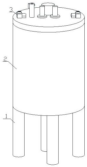
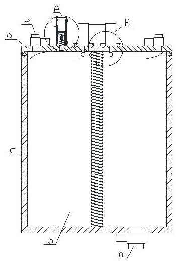
[0024] see figure 1 , figure 2 , image 3 and Figure 4 , the present invention provides a solution preparation equipment for industrial enzyme preparation: its structure includes a supporting foot rod 1, a blending tank 2, an electric control valve 3, the bottom end of the blending tank 2 is fixedly connected with a supporting foot rod 1, and the blending tank 2 is provided with an electric control valve 3;

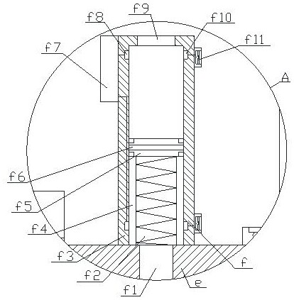
[0025] The blending tank 2 includes a discharge joint a, a blending tank b, a main tank body c, a tank cover d, a feed joint e, a high-pressure warning device f, and a stirring device g. The bottom end of the main tank body c is provided with a discharge Joint a, the inside of the main tank c is equipped with a blending tank b, the top of the main tank c is covered and locked with a tank cover d, and the left and right sides of the top of the tank cover d are provided with feed joints e, so The stirring device g is locked on the tank cover d, and the left side of th...


PUM


Abstract

The invention discloses solution blending equipment for industrial enzyme preparation. The structure of the solution blending equipment comprises supporting leg rods, a blending tank and an electric control valve. The solution blending equipment has the following beneficial effects that a threaded rod is arranged in the blending tank of the equipment and matched with a ball, an impeller plate assembly ring connected with the threaded rod and an impeller plate, and an electric telescopic rod is arranged at the top end of a tank cover for control, so that the equipment can drive the impeller plate to rotate by pressing the impeller assembly plate up and down,and the lifting stirring function is achieved; the equipment is simple in structure, and occupied space and cleaning dead angles are reduced; a pressure detection pipe body is arranged at the top end of the equipment tank cover; a pressure measuring groove is formed in the pipe body, and a piston plate supported through a compression spring is arranged in the middle of the pressure measuring groove; an electrifying plate is arranged in the middle of the piston plate and matched with warning indicator electrifying plates arranged on the upper side and the lower side of the pressure measuring groove, so that the equipment can drive the piston plate to descend or ascend to a certain degree when the negative pressure or the positive pressure in the blending groove is too high, an alarm is triggered, and danger treatment is better carried out when the equipment pressure is abnormal.

Description

technical field [0001] The invention belongs to the technical field of solution preparation equipment for industrial enzyme preparation, and in particular relates to a solution preparation equipment for industrial enzyme preparation. Background technique [0002] In the current industrial production, industrial enzymes are needed to promote the speed of industrial production. Usually, industrial enzymes are needed to regulate the rate of solution preparation, and the production efficiency can be improved by controlling the reaction rate. However, in the accelerated production process using industrial enzymes, it is often necessary to carry out The deployment of solutions for industrial enzyme preparation. These solution preparation equipment specially used for specific industrial enzyme preparation are solution preparation equipment for industrial enzyme preparation. With the rapid development of science and technology, technical improvements have also been made, but the exis...

Claims


Application Information

Patent Timeline
Patent Type & Authority Applications(China)
IPC IPC(8): B01F11/00B01F13/06B01F15/00
Inventor 邹千秋
Owner 邹千秋
Learn More