Capacitor film cleaning equipment for preventing overlapping through centrifugal force

A technology for capacitor film and cleaning equipment, which is applied to cleaning methods using tools, cleaning methods using liquids, capacitors, etc., can solve problems such as incomplete cleaning, low impact strength of polystyrene films, and reduced electrical performance of capacitors. Improve cleaning efficiency and effect, promote cavitation effect, and increase the effect of cleaning dead angle

Active Publication Date: 2019-05-03
苏州市东挺河智能科技发展有限公司
View PDF8 Cites 6 Cited by
  • Summary
  • Abstract
  • Description
  • Claims
  • Application Information

AI Technical Summary

Problems solved by technology

[0004] Aiming at the deficiencies in the prior art, the purpose of the present invention is to provide a capacitor film cleaning device that utilizes centrifugal force to prevent overlapping, so as to solve the problem of prior art that the polystyrene film is placed inside the cleaning chamber and then ultrasonic waves are used to clean the capacitor film. Cavitation effect, the polystyrene film is flipped and vibrated, and the polystyrene films collide with each other during the flip, but the impact strength of the polystyrene film itself is low, and it is easy to be damaged by force, and the polystyrene film does not Heat resistance, and when the temperature of ultrasonic cleaning is low, the effect of cavitation effect is small. At this time, the surface is completely washed by the accelerated water flow to clean the polystyrene film, and the polystyrene film will be affected by the water tension in water. Bonding together, resulting in less thorough cleaning and reducing the defects in the electrical properties of the processed capacitors

Method used


Image

  • Capacitor film cleaning equipment for preventing overlapping through centrifugal force
  • Capacitor film cleaning equipment for preventing overlapping through centrifugal force
  • Capacitor film cleaning equipment for preventing overlapping through centrifugal force

Examples


Embodiment Construction

[0028] In order to make the technical means, creative features, goals and effects achieved by the present invention easy to understand, the present invention will be further described below in conjunction with specific embodiments.

[0029] Such as Figure 1-7 As shown in the figure, the present invention provides a technical solution for capacitor film cleaning equipment that utilizes centrifugal force to prevent overlapping:

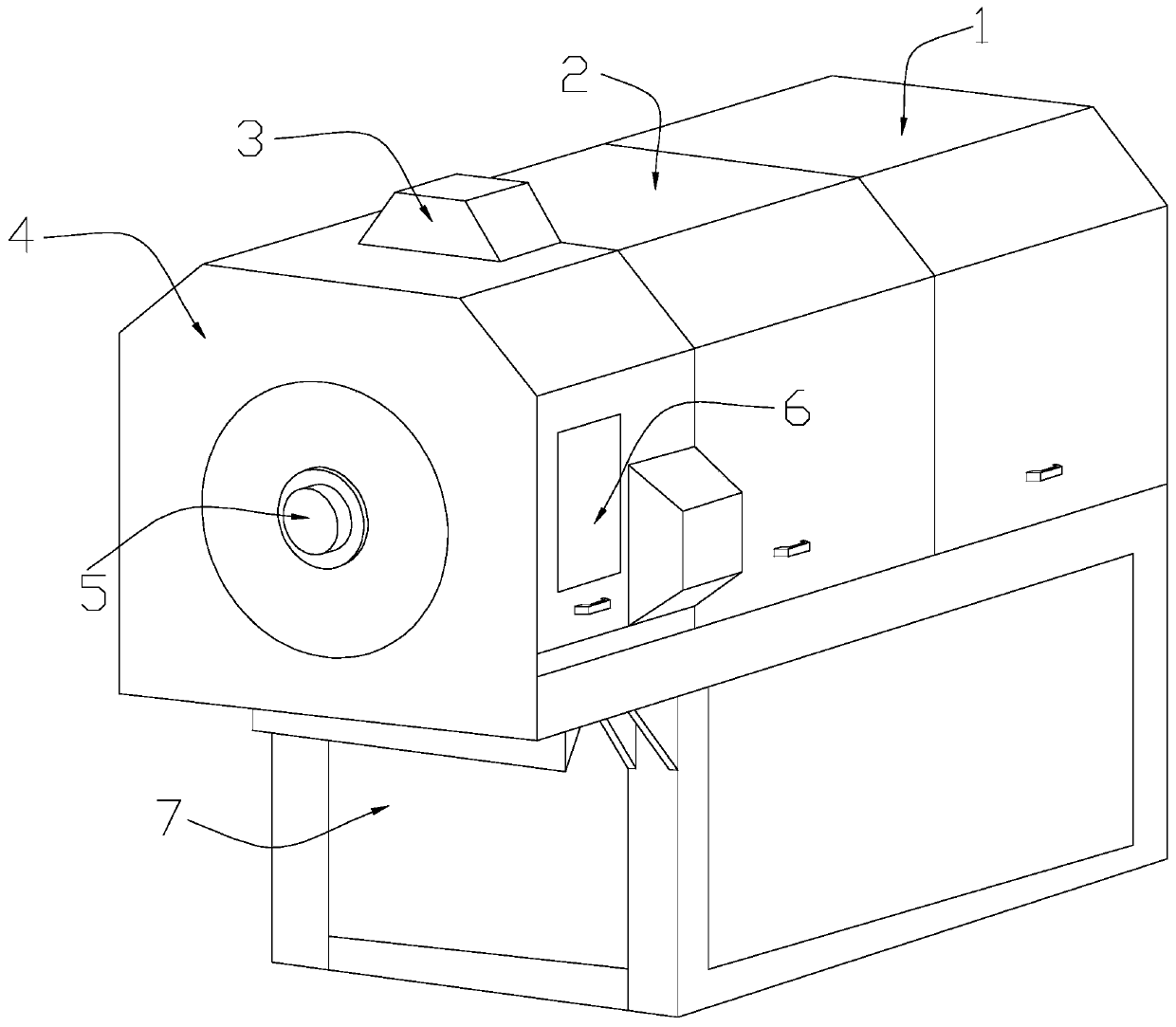
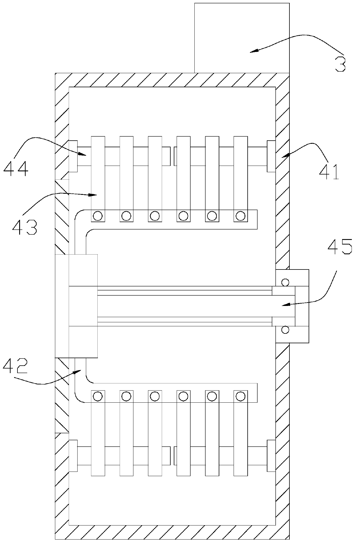
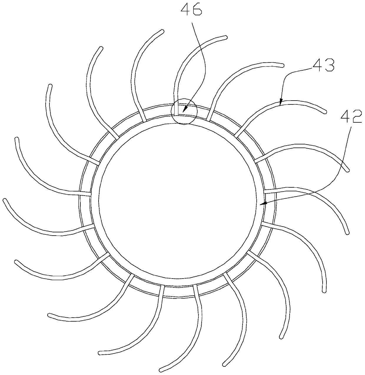
[0030] Such as Figure 1-3 As shown, a capacitor film cleaning device using centrifugal force to prevent overlapping, its structure includes a processing chamber 1, an auxiliary chamber 2, an ultrasonic wave 3, an anti-overlapping device 4, a driving shaft 5, an observation window 6, and a support seat 7. The processing The chamber 1 is installed on the right side of the auxiliary chamber 2, and the left side of the auxiliary chamber 2 is provided with an anti-overlapping device 4 and is connected by bonding. The outer surface of the anti-overlapping ...


PUM


Abstract

The invention discloses capacitor film cleaning equipment for preventing overlapping through centrifugal force. The capacitor film cleaning equipment structurally comprises a treatment cavity, an auxiliary cavity, an ultrasonic generator, an anti-overlapping device, a driving rotary shaft, an observation window and a supporting base. According to the capacitor film cleaning equipment, by means ofthe acting force of an electromagnet on an armature, films are clamped by a limiting plate and a clamping piston, the driving rotary shaft is utilized for driving a fixed frame and the film to rotateat uniform speed, so that the films bear the function of centrifugal force to spread all around to be in the shape of an arc paddle wheel, and it is avoided that the films are attached due to tensionof water, and consequently dead cleaning corners are increased; rotation of a main rod driven by friction force of the films is hindered through the deformation resistance of a torsion spring, and thesurfaces of the films are wiped and cleaned; airflow introduced into a main stem is increased through steering reducing of a stopping block and a branched channel, then fine bubbles are sprayed out of a spray head, generation of a cavitation effect is promoted, and the cleaning efficiency and effect on the films are improved.

Description

technical field [0001] The invention relates to the field of cleaning equipment, more specifically, a capacitor film cleaning equipment that utilizes centrifugal force to prevent overlapping. Background technique [0002] With the advancement of science and technology, the upgrading of electronics, home furnishing, communication and other industries is getting faster and faster, and film capacitors have become indispensable electronic components due to their good electrical performance and high reliability. In order to ensure their performance, they are being manufactured Previously, it was necessary to clean the polystyrene film of the capacitor. At present, ultrasonic cleaning is mostly used for vibration cleaning. The existing traditional technology is not comprehensive, and has the following disadvantages: [0003] When cleaning, the polystyrene film is put into the cleaning chamber, and then through the ultrasonic cavitation effect, the polystyrene film is flipped and v...

Claims


Application Information

Patent Timeline
Patent Type & Authority Applications(China)
IPC IPC(8): B08B1/02B08B3/10H01G13/00
Inventor 李三查
Owner 苏州市东挺河智能科技发展有限公司
Why Eureka
Try Eureka