
Bidirectional current-limiting DC current limiter

A current limiter and current limiting technology, applied in the field of current limiters, can solve the problems of small size of equipment, reduced economy, and low manufacturing cost.

Pending Publication Date: 2021-12-28
GUANGDONG POWER GRID CO LTD +1
View PDF0 Cites 0 Cited by
  • Summary
  • Abstract
  • Description
  • Claims
  • Application Information

AI Technical Summary

Problems solved by technology

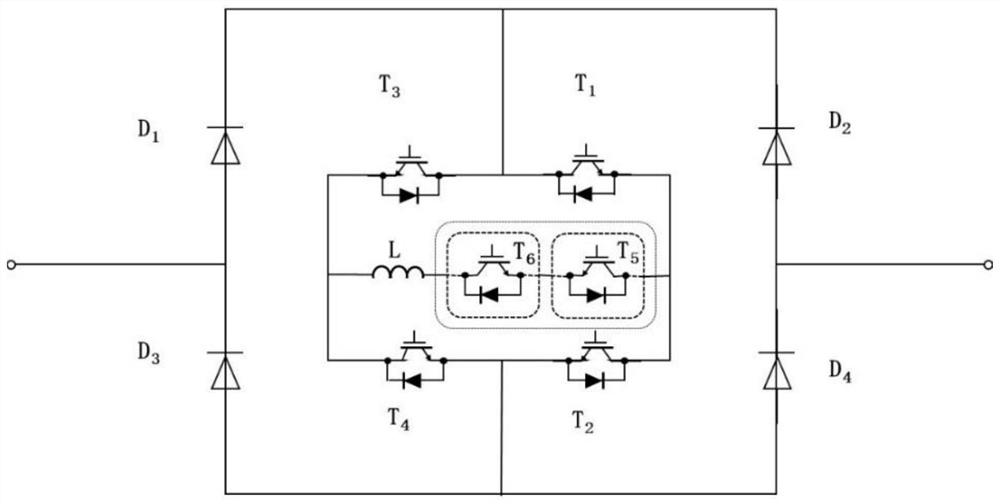
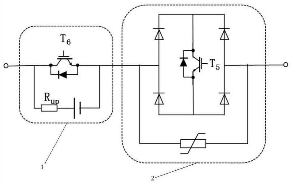
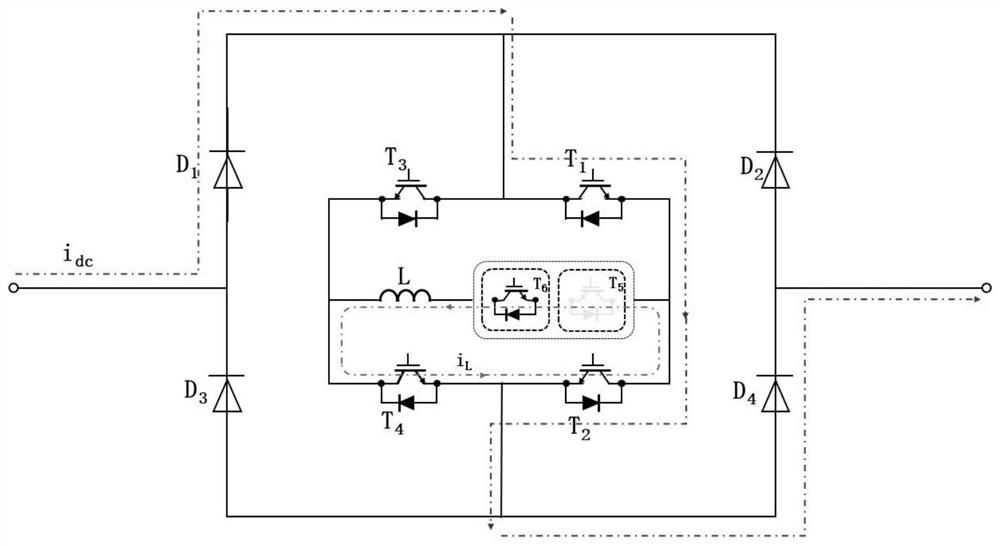
[0005] The invention provides a bidirectional current-limiting DC current limiter, which can meet the requirements of low manufacturing cost, small equipment size, and overcome the problem of economical decline as much as possible.

Method used


Image

  • Bidirectional current-limiting DC current limiter
  • Bidirectional current-limiting DC current limiter
  • Bidirectional current-limiting DC current limiter

Examples


Embodiment Construction

[0035] The technical solutions of the present application will be clearly and completely described below in conjunction with the accompanying drawings. Apparently, the described embodiments are some of the embodiments of the present application, not all of them. Based on the embodiments in this application, all other embodiments obtained by persons of ordinary skill in the art without making creative efforts belong to the scope of protection of this application.

[0036] In the description of this application, it should be noted that the terms "center", "upper", "lower", "left", "right", "vertical", "horizontal", "inner", "outer" etc. The indicated orientation or positional relationship is based on the orientation or positional relationship shown in the drawings, and is only for the convenience of describing the present application and simplifying the description, rather than indicating or implying that the referred device or element must have a specific orientation, use a spec...


PUM


Abstract

The invention discloses a bidirectional current-limiting DC current limiter, and the current limiter comprises an input end, a current-limiting branch, a current conversion branch and an output end; the commutation branch comprises an external circuit commutation branch and an internal circuit commutation branch. When the bidirectional current-limiting DC current limiter is in an on-state, the bidirectional current-limiting DC current limiter is connected in series with a DC line, and when a fault occurs, current limiting can be instantaneously put into use, so the system instability caused by rapid current rise at the beginning of the fault is avoided; meanwhile, the bidirectional current-limiting DC current limiter realizes bidirectional current limiting of the current limiter through four diodes, and the system mainly adopts the diodes and IGBTs as switching devices, so that the cost is relatively low, and the investment is relatively saved; besides, the bidirectional current-limiting DC current limiter realizes the conversion of DC current into high-frequency AC current by controlling the alternative conduction of the IGBT, and can control the disconnection of the DC circuit breaker especially when the current is close to 0, thereby greatly improving the disconnection reliability of the DC circuit breaker and reducing the removal capacity of the DC circuit breaker.

Description

technical field [0001] The invention relates to the technical field of current limiters, in particular to a bidirectional current limiting DC current limiter. Background technique [0002] Current DC current limiters mainly include solid-state current limiters and superconducting current limiters. The superconducting current limiter uses the physical properties of superconductors to automatically quench when the current rises sharply. The fault signal immediately connects a resistor or inductor in series in the fault circuit through the action of the power electronic device, thereby preventing the fault current from rising further. [0003] Both of the above two current limiters have inherent weaknesses: In order to meet the high voltage and large power requirements, solid-state current limiters often require a large number of devices to be connected in series and parallel, which will cause on-state loss, which will lead to economic decline; the manufacturing cost of superc...

Claims


Application Information

Patent Timeline
IPC IPC(8): H02H9/02H02H7/26
CPCH02H9/025H02H7/268Y02E60/60
Inventor 赵紫辉钱利宏杨昆刘尧郭晓燕向真李建标刘超赵晓燕
Owner GUANGDONG POWER GRID CO LTD
Learn More