A multi-frequency co-phase planar array directional sound wave emission device

A technology of directional emission and planar array, which is applied in the direction of fluid using vibration, etc., can solve the problems of large equivalent diameter and limited emission power

Active Publication Date: 2022-03-25
TSINGHUA UNIV
View PDF7 Cites 0 Cited by
  • Summary
  • Abstract
  • Description
  • Claims
  • Application Information

AI Technical Summary

Problems solved by technology

The device driven by electric energy can be designed as a planar array, and its equivalent diameter can be larger. For example, the frequency of the device composed of piezoelectric ceramic components can also be very high, that is, the directivity of this type of device is good, but it is limited by The performance limitation of electric components, its transmission power is limited

Method used


Image

  • A multi-frequency co-phase planar array directional sound wave emission device
  • A multi-frequency co-phase planar array directional sound wave emission device
  • A multi-frequency co-phase planar array directional sound wave emission device

Examples


Embodiment Construction

[0044] In order to make the purpose, technical solution and advantages of the present application clearer, the present application will be further described in detail below in conjunction with the accompanying drawings and embodiments. It should be understood that the specific embodiments described here are only used to explain the present application, not to limit the present application.

[0045] On the contrary, this application covers any alternatives, modifications, equivalent methods and schemes within the spirit and scope of this application as defined by the claims. Further, in order to make the public have a better understanding of the application, some specific details are described in detail in the detailed description of the application below. The present application can be fully understood by those skilled in the art without the description of these detailed parts.

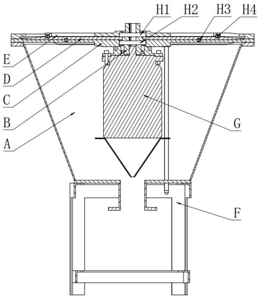
[0046] See figure 1 , the main components include cylinder A, central shaft B, fixed disk C, rot...


PUM


Abstract

The multi-frequency and same-phase planar array directional sound wave emission device provided by the present disclosure includes a cylinder; a driving part is installed in the cylinder, and the output end of the driving part is connected to a central shaft; a fixed plate is sleeved on the central shaft and connected to the cylinder The upper port of the cylinder is fixedly connected to become the upper seal of the cylinder. The fixed disc is punched at equal intervals in the radial direction, and a number of ventilation holes are evenly distributed on the circumference of the equal diameter; the rotating disc is sleeved on the central axis and located between the fixed disc. and is driven to rotate by the driving part. There are a number of air injection holes corresponding to the air holes in the radial direction on the rotating disk. The number of air injection holes on each circumference is different from the number of air holes to generate multiple frequency; The central shaft is located on the rotating disk, and is fixedly connected with the upper port of the cylinder. The sound wave of the device is directly emitted in the form of a planar array; the phase of the sound wave is guaranteed to be the same, and the multi-frequency acoustic wave acoustic parameter array greatly improves the directivity of the sound wave, which can realize the large-energy long-distance directional transmission of the sound wave.

Description

technical field [0001] The disclosure belongs to the field of transmitting energy by means of sound waves, and in particular relates to a device for directional emission of sound waves by a plane array with multiple frequencies and the same phase. Background technique [0002] Sound can transmit energy and information in the form of waves, but it is generally difficult to transport matter over long distances. [0003] The main parameters of sound wave transmission include intensity, directivity and frequency f or wavelength λ (λ=C 0 / f), the propagation speed of sound waves in air C 0 About 340m / s. The intensity of the sound wave is divided into sound pressure intensity and power intensity; after the sound wave is emitted, it will spread according to the spherical surface, and the direction of the sound source is taken as the main axis. On a certain spherical surface away from the sound source, the ratio of the intensity of any point to the main axis intensity is called D...

Claims


Application Information

Patent Timeline
Patent Type & Authority Patents(China)
IPC IPC(8): B06B1/18B06B3/00
CPCB06B1/18B06B3/00
Inventor 苏洋李铁键任海涛王光谦王兴奎
Owner TSINGHUA UNIV
Why Eureka
Try Eureka