Flexible continuum structure capable of being integrally driven and flexible mechanical arm

An integral drive, continuum technology, applied in the field of flexible manipulators, can solve problems such as complex structure, and achieve the effect of simple principle, high reliability, and high degree of freedom configuration

Active Publication Date: 2021-12-31
北京术锐机器人股份有限公司
View PDF8 Cites 1 Cited by
  • Summary
  • Abstract
  • Description
  • Claims
  • Application Information

AI Technical Summary

Problems solved by technology

[0003] However, since the above two driving methods are directly pushing and pulling the driving wire to move, when the

Method used


Image

  • Flexible continuum structure capable of being integrally driven and flexible mechanical arm
  • Flexible continuum structure capable of being integrally driven and flexible mechanical arm
  • Flexible continuum structure capable of being integrally driven and flexible mechanical arm

Examples


Embodiment 1

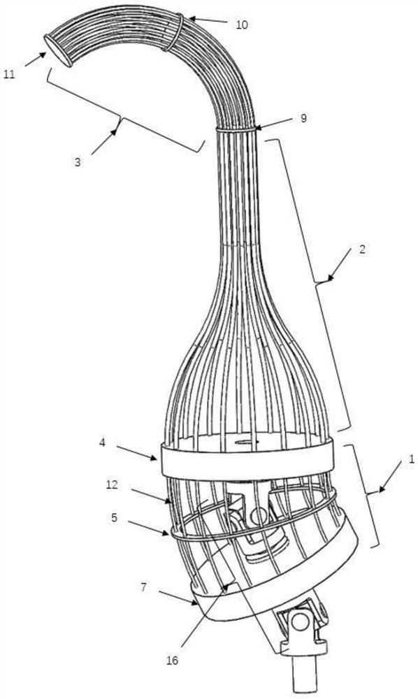
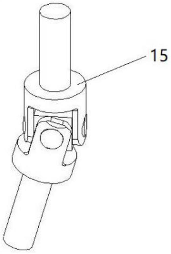
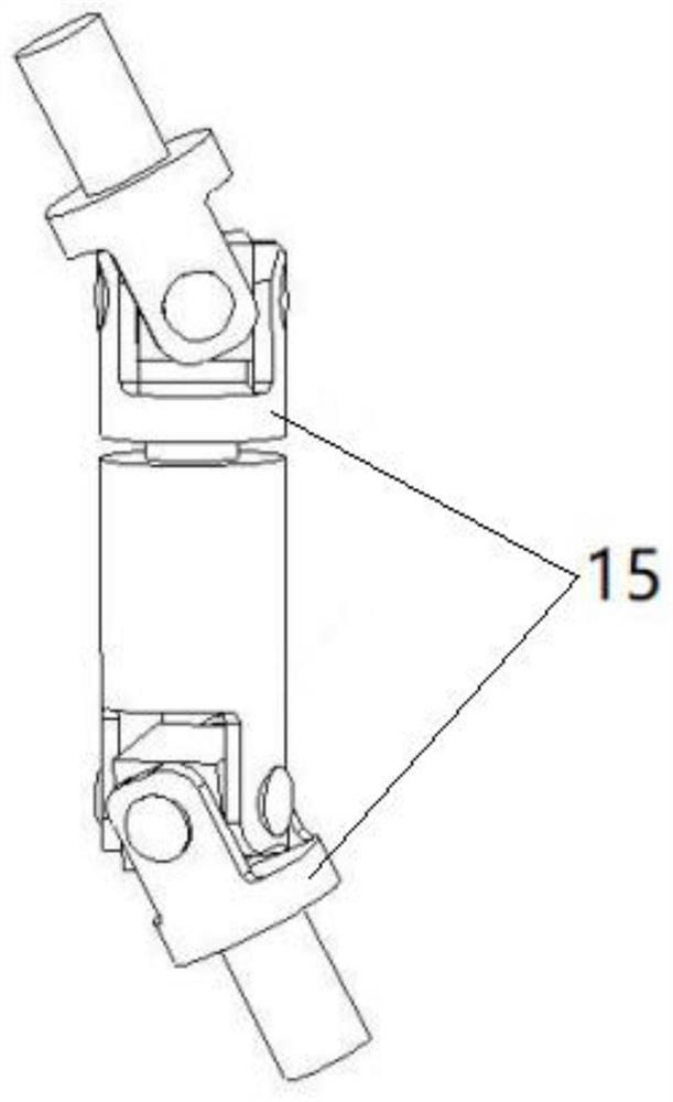
[0048] Such as Figure 1 to Figure 3 As shown, the drive connection part 16 in this embodiment may include one universal joint 15 or a plurality of universal joints 15 connected in series, one end of the drive connection part 16 is connected to the proximal base plate 4, and the other end of the drive connection part 16 passes through Pass the proximal stop disc 7 and connect with the proximal stop disc 7, the part of the drive connection part 16 located on the proximal side of the proximal stop disc 7 forms a free end connected to the external drive mechanism, and the drive connection part 16 is driven to move by the drive mechanism, Drive the proximal stop disc 7 to move and overturn, realize the pushing and pulling of the structural bone 12, and thus realize the bending of the distal continuum 3 along different directions in space.

[0049] In the first case, if figure 2 As shown, when the drive connection part 16 includes a universal joint 15, the far end of the drive co...

Embodiment 2

[0065] Such as Figure 4 to Figure 6 As shown, the drive connection part 16 provided in this embodiment may include a ball joint 17 or a plurality of ball joints 17 in series, the distal end of the drive connection part 16 is connected to the proximal base plate 4, and the proximal end of the drive connection part 16 passes through The proximal stop disc 7 is connected with the proximal stop disc 7, and the part of the drive connection part 16 located at the proximal side of the proximal stop disc 7 forms a free end for connecting with an external drive mechanism, and the drive connection part 16 is externally connected to the drive mechanism to drive The movement of the proximal disc 7 reverses to realize the pushing and pulling of the structural bone 12 , thereby realizing the bending of the distal continuum 3 in different directions in space.

[0066] It can be understood that the driving connection part 16 includes at least one ball joint 17 and at least one connecting rod...

Embodiment 3

[0079] Such as Figure 7 to Figure 9 As shown, the drive connection part 16 provided in this embodiment may include a hinge joint, the distal end of the drive connection part 16 is connected to the proximal base plate 4, and the proximal end of the drive connection part 16 passes through the proximal stop disc 7 and connects with the proximal end The stop disc 7 is connected, and the part of the drive connection part 16 located on the proximal side of the proximal stop disc 7 forms a free end for connecting with an external drive mechanism, and the drive connection part 16 is externally connected to the drive mechanism to drive the proximal stop disc 7 to move and overturn , to realize the pushing and pulling of the structural bone 12, thereby realizing the bending of the distal continuum 3 along different directions in space.

[0080] Specifically, the driving connection part 16 includes at least one distal connecting rod and at least one proximal connecting rod hinged to for...


PUM


Abstract

The invention relates to a flexible continuum structure capable of being integrally driven and a flexible mechanical arm, comprising: a near-end continuum comprising a near-end basal disc, a near-end stop disc and a structural bone; a far-end continuum comprising a far-end basal disc, a far-end stopping disc and the structural bone; and a driving connecting part, wherein one end of the driving connecting part is connected with the near-end basal disc, the other end of the driving connecting part penetrates through the near-end stop disc and is connected with the near-end stop disc, and the part, located on the near-end side of the near-end stop disc, of the driving connecting part forms a free end. The near ends of the multiple structural bones are fixedly connected with the near-end stop disc, and the far ends of the multiple structural bones sequentially pass through the near-end basal disc and the far-end basal disc and then are fixedly connected with the far-end stop disc. A driving wire can be prevented from being directly pushed and pulled, limitation to the number of driving mechanisms can be avoided, the bending performance of the flexible continuum structure is met, and meanwhile the flexible continuum structure is compact in structure, simple in principle, easy to implement and high in reliability.

Description

technical field [0001] The invention relates to a continuum structure, in particular to a flexible continuum structure that can be integrally driven and a flexible mechanical arm comprising the flexible continuum structure. Background technique [0002] The existing continuum structure generally directly pushes and pulls the driving wire in the continuum structure through the driving mechanism, and the driving of the driving wire is divided into two types: the first is to directly push and pull the wire through the linear pair, so as to drive the flexible manipulator to bend The second is to push and pull a group of thicker driving wires through the linear pair to make the proximal continuum bend, thereby driving a group of thinner driving wires on the proximal continuum to bend to drive the flexible manipulator to bend. Thereby, it is realized to drive more driving wires with a smaller number of driving mechanisms. [0003] However, since the above two driving methods are ...

Claims


Application Information

Patent Timeline
IPC IPC(8): B25J18/00B25J17/00B25J9/10
CPCB25J18/005B25J17/00B25J9/10
Inventor 徐凯刘旭
Owner 北京术锐机器人股份有限公司
Why Eureka
Try Eureka