Building foundation pit supporting structure with damping structure

A foundation pit support and construction technology, which is used in construction, infrastructure engineering, sheet pile walls, etc. The effect of increased tightening force and simple equipment structure

Inactive Publication Date: 2021-12-31
王涛
View PDF0 Cites 0 Cited by
  • Summary
  • Abstract
  • Description
  • Claims
  • Application Information

AI Technical Summary

Problems solved by technology

[0002] The most common place where foundation pit support is applied is at the construction site. Generally, the mountain is excavated, or after the hole is dug on the ground, it is necessary to install and support the corresponding exposed soil slope to prevent soil collapse or water liquid. The entry of the foundation pit caused the flooding or collapse of the foundation pit. In this process, the most commonly used support is concrete support, and the mesh support that blocks the soil slope. In the process of using mesh support , the method is to spread the mesh support and then use nails to lock the different positions of the mesh support and then install it on the soil slope. The most common disadvantage of the mesh support in the process of use is that, Only a few points can be locked and installed, but the corresponding mesh structure cannot be tightened, so that the protective net has a good pre-tightening force to prevent the corresponding soil blocks from slipping, etc., and the installation process is due to the pre-tightening needs Large force, the existing equipment can not solve this problem very well

Method used


Image

  • Building foundation pit supporting structure with damping structure
  • Building foundation pit supporting structure with damping structure
  • Building foundation pit supporting structure with damping structure

Examples


Embodiment Construction

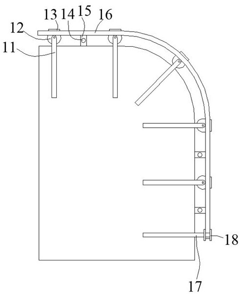
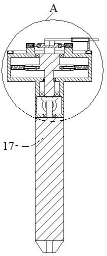
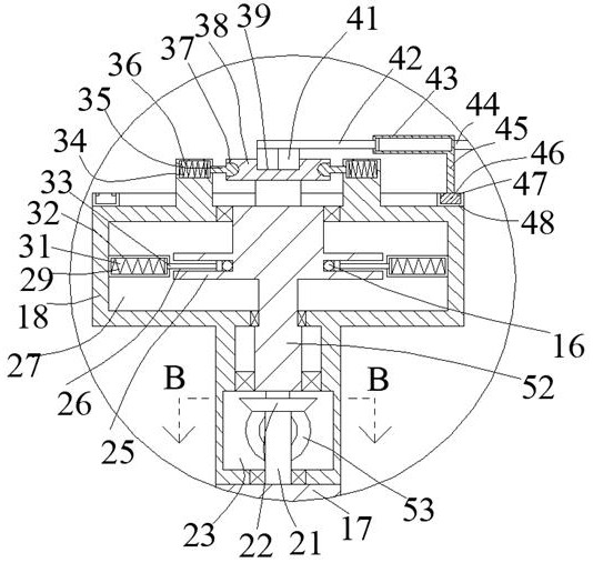
[0024] Such as Figure 1-Figure 9 As shown, the present invention is described in detail. For the convenience of description, the orientations mentioned below are now stipulated as follows: figure 1 The up, down, left, right, front and back directions of the projection relationship are consistent. A building foundation pit support structure with a shock absorbing structure of the present invention includes several strip-shaped stay ropes 16, and the lower side of the stay ropes 16 is provided with a locking block 15. The locking block 15 is provided with a matching rope 14 perpendicular to the pull rope 16, the matching rope 14 and the pulling rope 16 form a mesh structure, and the ends of the pulling rope 16 and the matching rope 14 are provided with a matching box body 18, the stay rope 16 and the matching rope 14 extend into the matching box 18 for winding, and one side of the matching box 18 is provided with a rotating drilling rod 17, and the pulling rope 16 and the match...


PUM


Abstract

The invention discloses a building foundation excavation retaining and protectingstructure with a damping structure. The building foundation excavation retaining and protecting structure comprises a plurality of strip-shaped pull ropes, locking blocks are arranged on the lower sides of the pull ropes, matching ropes perpendicular to the pull ropes are arranged in the locking blocks, the matching ropes and the pull ropes form a net-shaped structure, matching box bodies are arranged at the end parts of the pull ropes and the matching ropes, the pull ropes and the matching ropes extend into the matching box bodies for winding, a rotating drilling rod is arranged on one side of each matching box body, and backing plates are arranged at other positions of the pull ropes and the matching ropes. According to the building foundation excavation supporting structure, a net-shaped structure formed by the pull ropes and the matching ropes can be utilized, and transition wheels and the backing plates are utilized, so that the pull ropes and the matching ropes can slide more smoothly; and the drilling rods can be rotated, the pull ropes and the matching ropes can be pre-tightened and combined, so that the pull ropes and the matching ropes are locked on a slope surface after being pre-tightened, and the contact area between equipment and earthwork can be increased during pre-tightening, so that the pre-tightening force is increased.

Description

technical field [0001] The invention relates to the technical field of foundation pit support equipment, in particular to a building foundation pit support structure with a shock absorbing structure. Background technique [0002] The most common place where foundation pit support is applied is at the construction site. Generally, the mountain is excavated, or after the hole is dug on the ground, it is necessary to install and support the corresponding exposed soil slope to prevent soil collapse or water liquid. The entry of the foundation pit caused the flooding or collapse of the foundation pit. In this process, the most commonly used support is concrete support, and the mesh support that blocks the soil slope. In the process of using mesh support , the method is to spread the mesh support and then use nails to lock the different positions of the mesh support and then install it on the soil slope. The most common disadvantage of the mesh support in the process of use is tha...

Claims


Application Information

Patent Timeline
Patent Type & Authority Applications(China)
IPC IPC(8): E02D17/04E02D5/76
CPCE02D17/04E02D5/765
Inventor 王涛
Owner 王涛
Why Eureka
Try Eureka