Burner fire cover for gas stove and stove applying burner fire cover
A burner and gas stove technology, which is applied in the field of stoves, can solve problems such as overflow liquid blockage, gas stoves cannot maintain flames, and gas stoves do not ignite, so as to prolong the service life, improve the ignition success rate, and improve the use environment. Effect
- Summary
- Abstract
- Description
- Claims
- Application Information
AI Technical Summary
Problems solved by technology
Method used
Image

Examples
Embodiment 1
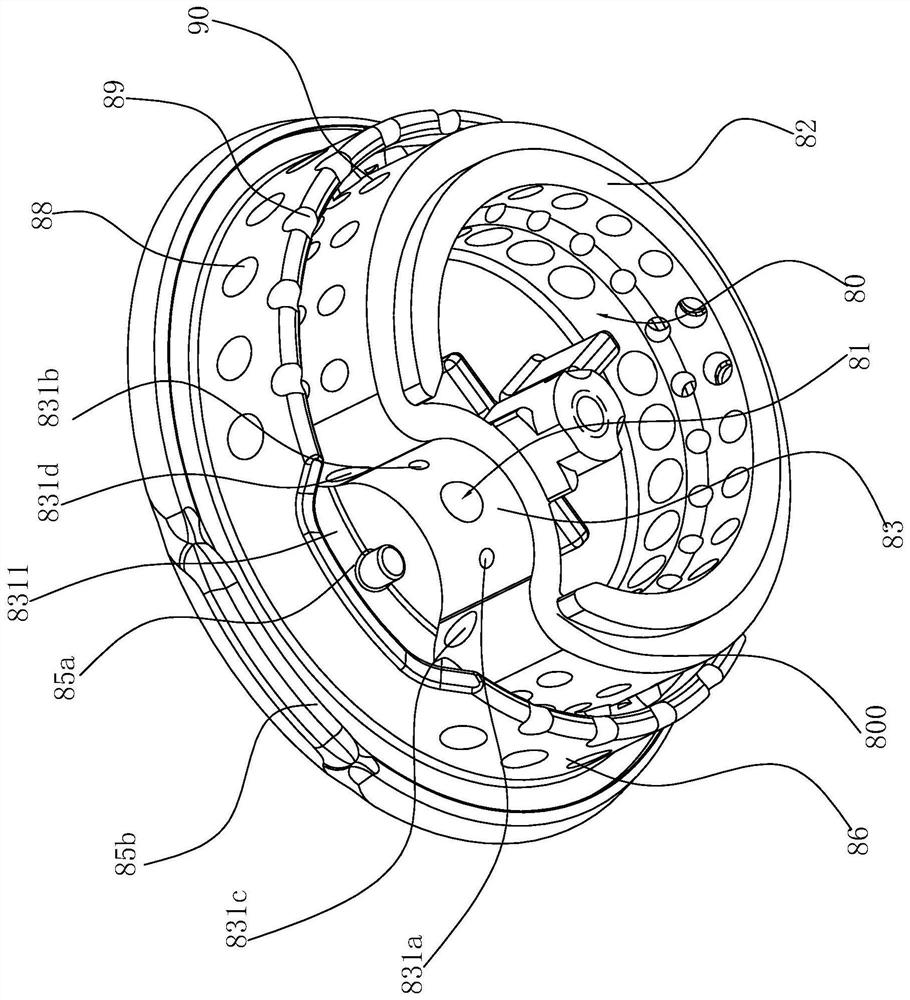
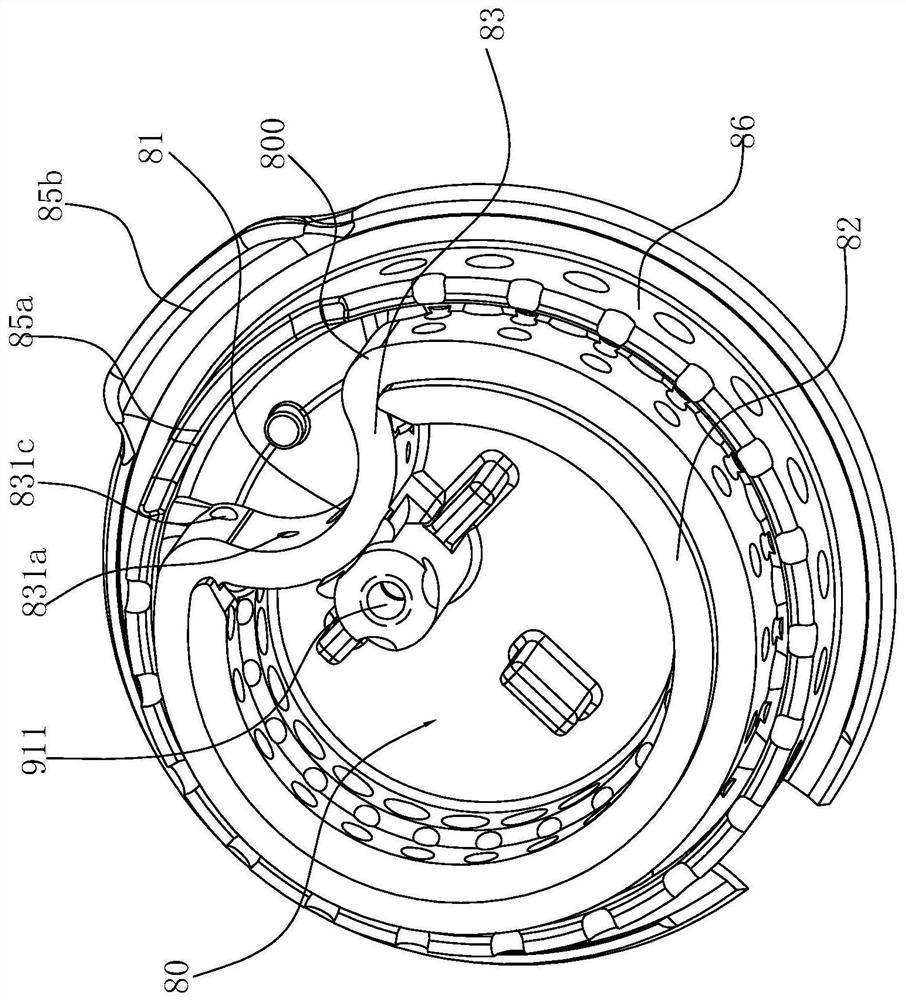
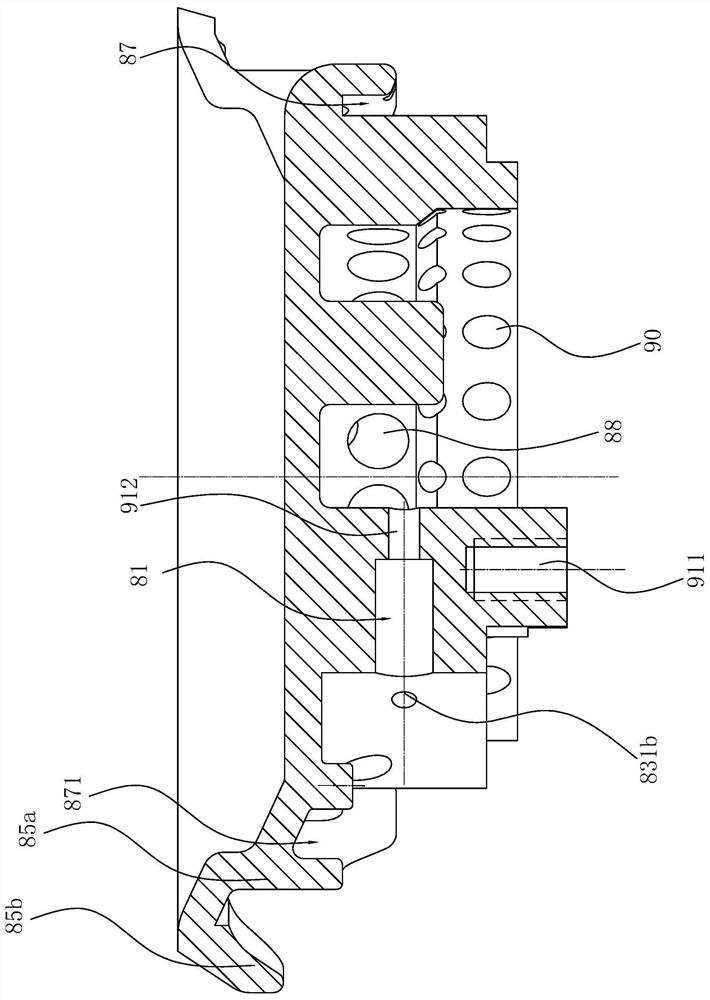
[0073] Such as Figure 1-13 Shown is the preferred embodiment of the present invention. The cooker of this embodiment includes a mounting base 1, a second gas mixing chamber 2 arranged on the periphery of the mounting base 1, and the second gas mixing chamber 2 includes an inner ring wall 21 and an outer ring wall 22 arranged concentrically at intervals and connecting The bottom wall 23 of the inner ring wall 21 and the outer ring wall 22, the inner ring wall 21 and the outer ring wall 22 are covered with the second fire cover 3, the inner ring wall 21, the outer ring wall 22, the bottom wall 23 and the second fire cover 3 are jointly set up to form the second gas mixing chamber 2; the second injection tube 4 arranged on the mounting base 1, the gas outlet 41 of the second injection tube 4 communicates with the second gas mixing chamber 2; and the same setting The second injector 5 that is on the mounting base 1 and communicates with the air inlet 42 of the second injection p...
Embodiment 2
[0078] Such as Figures 14 to 16As shown, the structure is basically the same as that of Embodiment 1, the only difference is that in order to further reduce the airflow velocity of the ignition hole, the positions corresponding to the first auxiliary ignition hole 831a and the second auxiliary ignition hole 831b on the C-shaped connecting wall are also respectively A first convex wall 832 and a second convex wall 833 extend radially inward, and the design of the first convex wall 832 and the second convex wall 833 can increase the gas outlet path of the first auxiliary ignition hole 831a and the second auxiliary ignition hole 831b , to reduce the airflow velocity of the first auxiliary ignition hole 831a and the second auxiliary ignition hole 831b, which can greatly increase the ignition success rate of the ignition cover, while the wall surfaces of the first convex wall 832 and the second convex wall 833 respectively face the respective corresponding The direction of the end...
Embodiment 3
[0080] Such as Figures 17-19 As shown, the structure is basically the same as that of Embodiment 2, the only difference is: in order to facilitate the user to lift the first fire cover 8 together when cleaning the burner, the C-shaped connecting wall is also provided with a connecting piece 700 The first installation hole 830 is installed, the first installation hole 830 is spaced apart from the through hole 81, and is connected to the first installation hole 830 by the connector 700, thereby connecting the first fire cover 8 to its corresponding base 7, with It is convenient to clean and at the same time, it can avoid the phenomenon that the user is easy to misplace the first burner 8 after cleaning the first burner 8. Correspondingly, in order to realize the connection of the first burner 8, the above-mentioned burner burner is used The C-shaped inner wall of the base 7 in the cooker has a connecting seat 730 extending upward, and the connecting seat 730 has a second mounti...
PUM
 Abstract
Description
Claims
Application Information
 - R&D Engineer
- R&D Manager
- IP Professional
- Industry Leading Data Capabilities
- Powerful AI technology
- Patent DNA Extraction
Browse by: Latest US Patents, China's latest patents, Technical Efficacy Thesaurus, Application Domain, Technology Topic.
© 2024 PatSnap. All rights reserved.Legal|Privacy policy|Modern Slavery Act Transparency Statement|Sitemap