Heat storage type burner used for radiant tube

A radiant tube and regenerative technology, applied in the direction of burner, combustion method, combustion type, etc., can solve the problems that the surface of the strip steel cannot reach the expected temperature, the spark plug affects the flame detection signal, and affects the coating effect of the strip steel product, etc. , to achieve high heat utilization rate, continuous and stable combustion state, and good heating effect

Inactive Publication Date: 2016-04-20
宝钢日铁汽车板有限公司
View PDF10 Cites 5 Cited by
  • Summary
  • Abstract
  • Description
  • Claims
  • Application Information

AI Technical Summary

Problems solved by technology

[0004] 1) The heat accumulator in the radiant tube is prone to damage during use and blocks the radiant tube, resulting in failures such as excessive exhaust gas temperature or failure to ignite normally
[0005] 2) The ignition burner in the radiant tube often has carbon deposits and short circuits on the head of the spark plug, which affects the flame detection signal, resulting in poor ignition reliability and low ignition success rate
[0006] 3) The heat storage body in the radiant tube is usually a multi-layer porous structure, which is easy to be misaligned between the upper and lower layers during the installation process, resulting in local airflow blockage, affecting the circulation of exhaust gas, and causing uneven heating of the heat storage body
[0007] The above three problems will cause the heating temperature of the radiant tube to be low, resulting in that the surface of the strip steel cannot reach the expected temperature, thereby affecting the coating effect of the strip steel product, thereby affecting the terminal quality of the product, and reducing the production capacity of the production line

Method used


Image

  • Heat storage type burner used for radiant tube
  • Heat storage type burner used for radiant tube
  • Heat storage type burner used for radiant tube

Examples


Embodiment Construction

[0054] The following will further illustrate the regenerative burner for radiant tubes according to the present invention according to specific embodiments and related drawings, but the specific embodiments and related descriptions do not constitute improper limitations to the technical solution of the present invention.

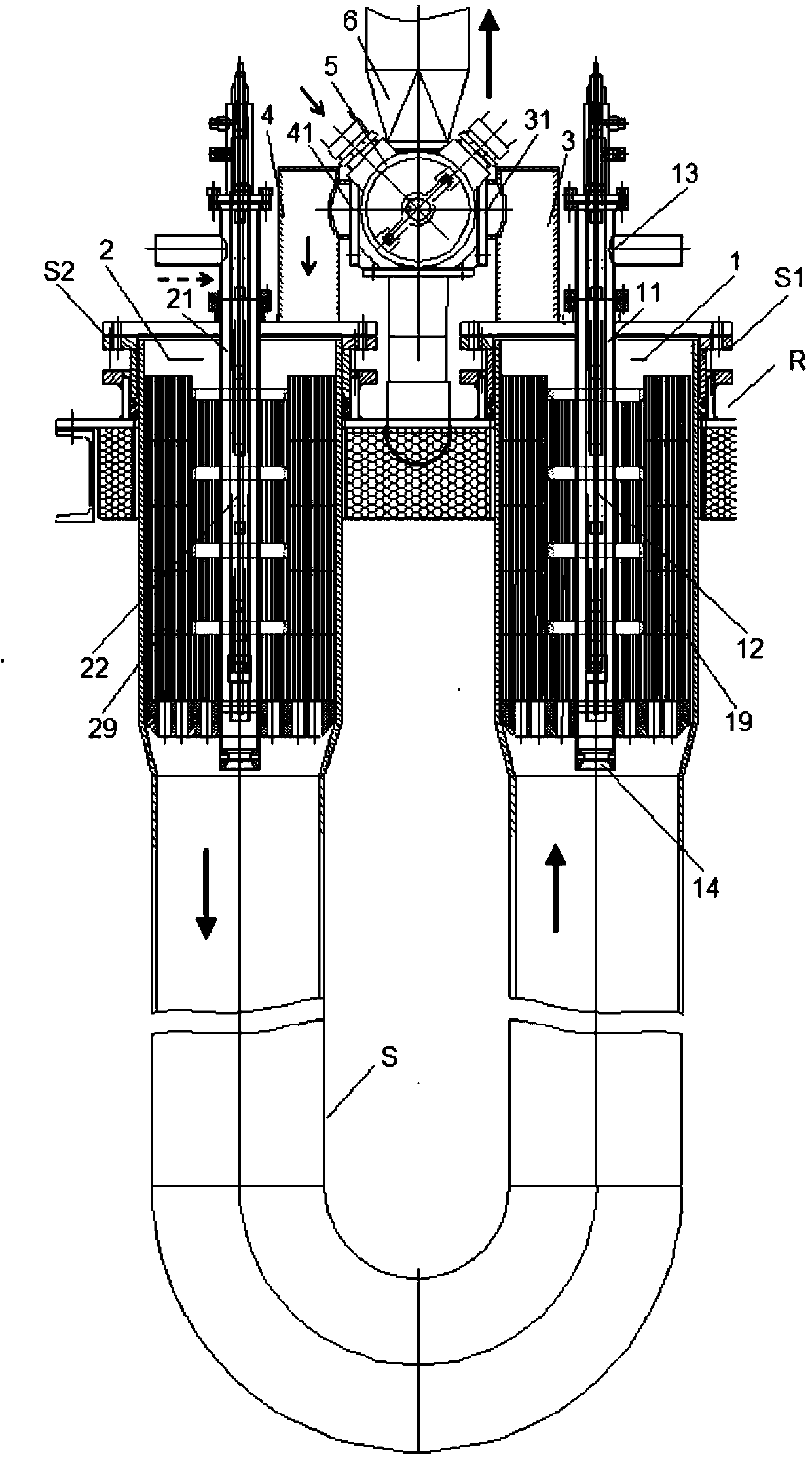
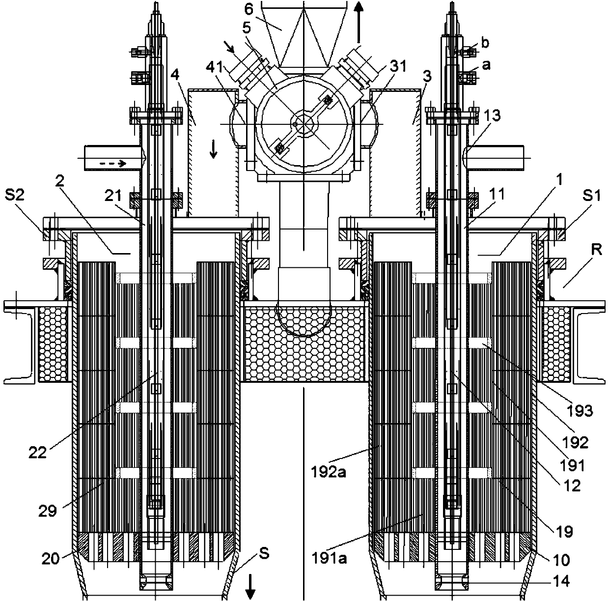
[0055] figure 1 and figure 2 The structures of the regenerative burners for radiant tubes according to the present invention in one embodiment are shown respectively.

[0056] In the following embodiments, the combustion-supporting gas is air, and the combustible gas is coal gas.

[0057] exist figure 1 The direction of the solid arrow in the figure represents the flow direction of air, the dashed arrow represents the flow direction of gas, and the bold arrow represents the flow direction of exhaust gas. figure 1 The reversing valve is shown in the first position.

[0058] like figure 1 and figure 2 As shown, the regenerative burner R for radiant tub...


PUM


Abstract

The invention discloses a heat storage type burner used for a radiant tube. The heat storage device is arranged in the radiant tube which is provided with two end parts; the two end parts of the radiant tube are respectively provided with a first burner assembly and a second burner assembly correspondingly; each of the first burner assembly and the second burner assembly comprises a heat storage body; the two end parts of the radiant tube are respectively provided with a first air pipeline and a second air pipeline which are communicated with the radiant tube correspondingly; each of the first air pipeline and the second air pipeline is provided with an air inlet; a reversing valve is connected to the first air pipeline and the second air pipeline; the reversing valve is stopped between a first station and the first air pipeline, and is communicated with the second air pipeline; the reversing valve is communicated with the first air pipeline at a second station, and is stopped between the second station and the second air pipeline; and a gas exhaust pipeline is communicated with the reversing valve. The heat storage type burner disclosed by the invention is high in ignition success rate and is good in combustion stability after ignition; a heat storage body is not liable to damage, heat storage capacity is high, and a waste gas heat utilization rate is high.

Description

technical field [0001] The invention relates to a burner, in particular to a burner for a radiant tube. Background technique [0002] The hot-dip galvanizing oven mainly uses radiant tubes to achieve heating. The existing radiant tube is equipped with a regenerative burner, the heating of the radiant tube is realized through the regenerative burner, and the heat is recovered from the waste gas to preheat the air, and the heated air is sprayed to the surface of the strip in circulation, Make the strip surface reach the expected temperature, so as to coat the strip surface after drying. [0003] The existing regenerative burners for radiant tubes have many advantages such as high combustion heat efficiency, energy saving and environmental protection, but in actual use, there are still the following problems: [0004] 1) The heat accumulator in the radiant tube is prone to damage during use and blocks the radiant tube, resulting in failures such as excessive exhaust gas tempe...

Claims


Application Information

Patent Timeline
Patent Type & Authority Applications(China)
IPC IPC(8): F23D14/12F23D14/48F23D14/66F23D14/46
CPCY02E20/34
Inventor 强晓彬王鲁顾希成曹璐
Owner 宝钢日铁汽车板有限公司
Why Eureka
Try Eureka