Ignition device and ignition method for sinter pot test
What is Al technical title?
Al technical title is built by PatSnap Al team. It summarizes the technical point description of the patent document.
An ignition device and technology for testing, applied in the direction of combustion ignition, combustion method, incandescent ignition, etc., can solve the problems that affect the ignition effect and the uniformity of combustion, separate combustion-supporting blower settings, poor operation synchronization, etc., to improve the fuel combustion effect , saving manpower and space, high ignition success rate
Active Publication Date: 2012-12-19
ANGANG STEEL CO LTD
View PDF5 Cites 5 Cited by
Summary
Abstract
Description
Claims
Application Information
AI Technical Summary
This helps you quickly interpret patents by identifying the three key elements:
Problems solved by technology
Method used
Benefits of technology
Problems solved by technology
[0003] In the previous sintering cup test, because the blower was far away from the sintering cup, two valves had to be opened at the same time when igniting, that is, the gas valve and the combustion fan valve, which required two people to cooperate at the same time, which not only wasted manpower, but also the synchronization of the operation was poor. , it is very easy to appear hysteresis on one side, which affects the ignition effect and the uniformity of combustion, and the combustion-supporting blower needs to be set up in a separate space, which causes a lot of inconvenience to the site
Method used
Image
Click on the blue label to locate the original text in one second.
Reading with bidirectional positioning of images and text.
Examples
Embodiment Construction
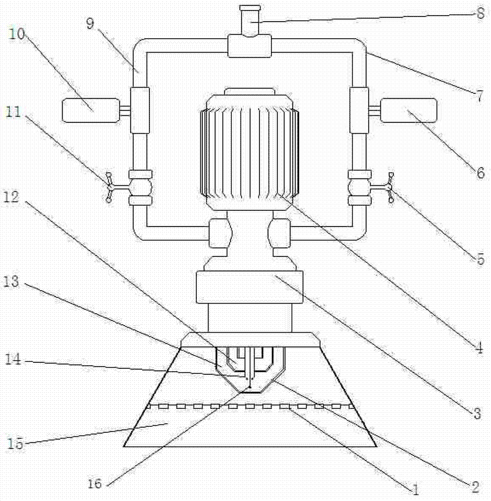
[0019] It can be seen from the accompanying drawings that the ignition device for the sintering cup test of the present invention consists of a flame distribution plate 1, a premixing chamber 2, a connecting seat 3, a blower 4, a main gas valve 5, a main solenoid valve 6, a main gas pipe 7, and a gas main pipe. 8. The auxiliary gas pipe 9, the auxiliary solenoid valve 10, the auxiliary gas valve 11, the gas outlet 12, the electronic igniter 14, the protective cover 15, the flame detection head 16 and the computer. The lower end of the blower 4 is provided with a combustion-supporting air pipe, and the protective cover 15 is fixed below the blower 4 by the connection seat 3, and the bottom of the connection seat 3, namely the protective cover 15, is provided with a premix chamber 2. The upper ends of the main gas pipe 7 and the auxiliary gas pipe 9 are respectively connected to the gas main pipe 8, and the main gas pipe 7 and the auxiliary gas pipe 9 are arranged on both sides o...
PUM
Abstract
The invention provides an ignition device and an ignition method for a sinter pot test. The ignition device is composed of a flame uniform distribution plate, a blast blower, an air tube, a gas valve, an electromagnetic valve, a primary gas tube, a secondary gas tube, a premixing cavity, a connection seat, an electronic igniter, a protective cover, a flame detector and a computer; the computer starts the blast blower, the electronic igniter, the flame detector and the secondary electromagnetic valve in a programmable manner for pre-igniting, and judges whether the pre-igniting is successful according to a set temperature; if the pre-igniting is not successful, the computer stops the secondary electromagnetic valve, and re-ignites; if the pre-igniting is successful, the computer starts the primary electromagnetic valve for formal igniting, and the computer times; and when the ignition time reaches a set time, the computer stops the primary electromagnetic valve, the secondary electromagnetic valve and the blast blower in a programmable manner. The ignition device and the ignition method for the sinter pot test provided by the invention can economize on manpower and space, ensure uniform and stable flame temperature at the outlet of the protective cover, and realize an automatic ignition control process; and with the ignition device and the ignition method, a combustion effect of fuel can be improved, and the accuracy rate of the sinter pot test can be ensured.
Description
technical field [0001] The invention belongs to the field of mechanical equipment, and in particular relates to an ignition device and an ignition method for igniting a mixture fuel during a sintering cup test. Background technique [0002] During the sintering cup test, it is necessary to ignite the fuel on the surface of the mixture, and then use the negative pressure generated by the exhaust fan to gradually move down the combustion layer, and finally complete the entire sintering process. [0003] In the previous sintering cup test, because the blower was far away from the sintering cup, two valves, namely the gas valve and the combustion fan valve, needed to be opened at the same time when igniting. Two people were required to cooperate with the operation at the same time, which not only wasted manpower, but also the synchronization of the operation was poor. , it is very easy to appear hysteresis on one side, which affects the ignition effect and the uniformity of comb...
Claims
Application Information
Patent Timeline
Application Date:The date an application was filed.
Publication Date:The date a patent or application was officially published.
First Publication Date:The earliest publication date of a patent with the same application number.
Issue Date:Publication date of the patent grant document.
PCT Entry Date:The Entry date of PCT National Phase.
Estimated Expiry Date:The statutory expiry date of a patent right according to the Patent Law, and it is the longest term of protection that the patent right can achieve without the termination of the patent right due to other reasons(Term extension factor has been taken into account ).
Invalid Date:Actual expiry date is based on effective date or publication date of legal transaction data of invalid patent.