Air discharge heating apparatus, system and method for diesel engine under full operating condition

A technology of a heating device and a heating method, which is applied to the electric control of the exhaust device and the exhaust gas treatment device, and the exhaust gas treatment, etc., can solve the problems of the catalyst falling off easily, the power consumption of the heating device being large, the structure of the regeneration system being complicated, etc. The effect of reducing regeneration energy consumption, extending regeneration mileage, and reducing accumulation rate

Inactive Publication Date: 2009-05-27
MILITARY TRANSPORTATION UNIV PLA
View PDF0 Cites 19 Cited by
  • Summary
  • Abstract
  • Description
  • Claims
  • Application Information

AI Technical Summary

Problems solved by technology

[0006] (1) Electric heating, microwave heating, and infrared heating are used for regeneration, and the energy conversion during the regeneration process will cause a large amount of energy loss; in addition, the energy required for regeneration basically comes from the battery, and the power consumption of the heating device during the regeneration process is large, which brings a lot of energy to the battery. For this reason, it is usually necessary to install a generator and adopt bypass regeneration, resulting in a complex structure of the regeneration system
[0007] (2) In-cylinder post-injection or exhaust pipe injection is used for fuel injection and combustion-supporting heating. In-cylinder post-injection is only suitable for high-pressure common rail diesel engines, and because part of the diesel oil will seep into the oil pan to dilute the engine oil, the engine wear w...

Method used


Image

  • Air discharge heating apparatus, system and method for diesel engine under full operating condition
  • Air discharge heating apparatus, system and method for diesel engine under full operating condition
  • Air discharge heating apparatus, system and method for diesel engine under full operating condition

Examples


Embodiment Construction
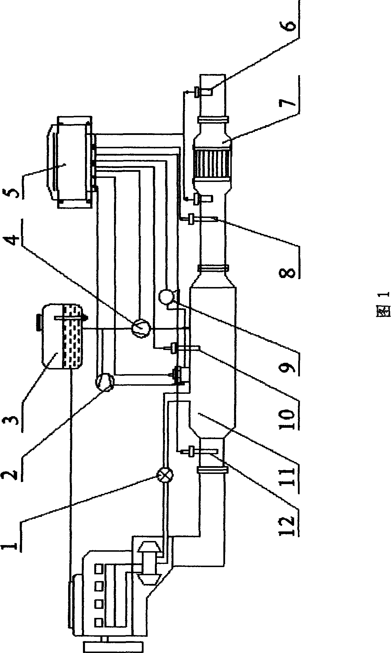
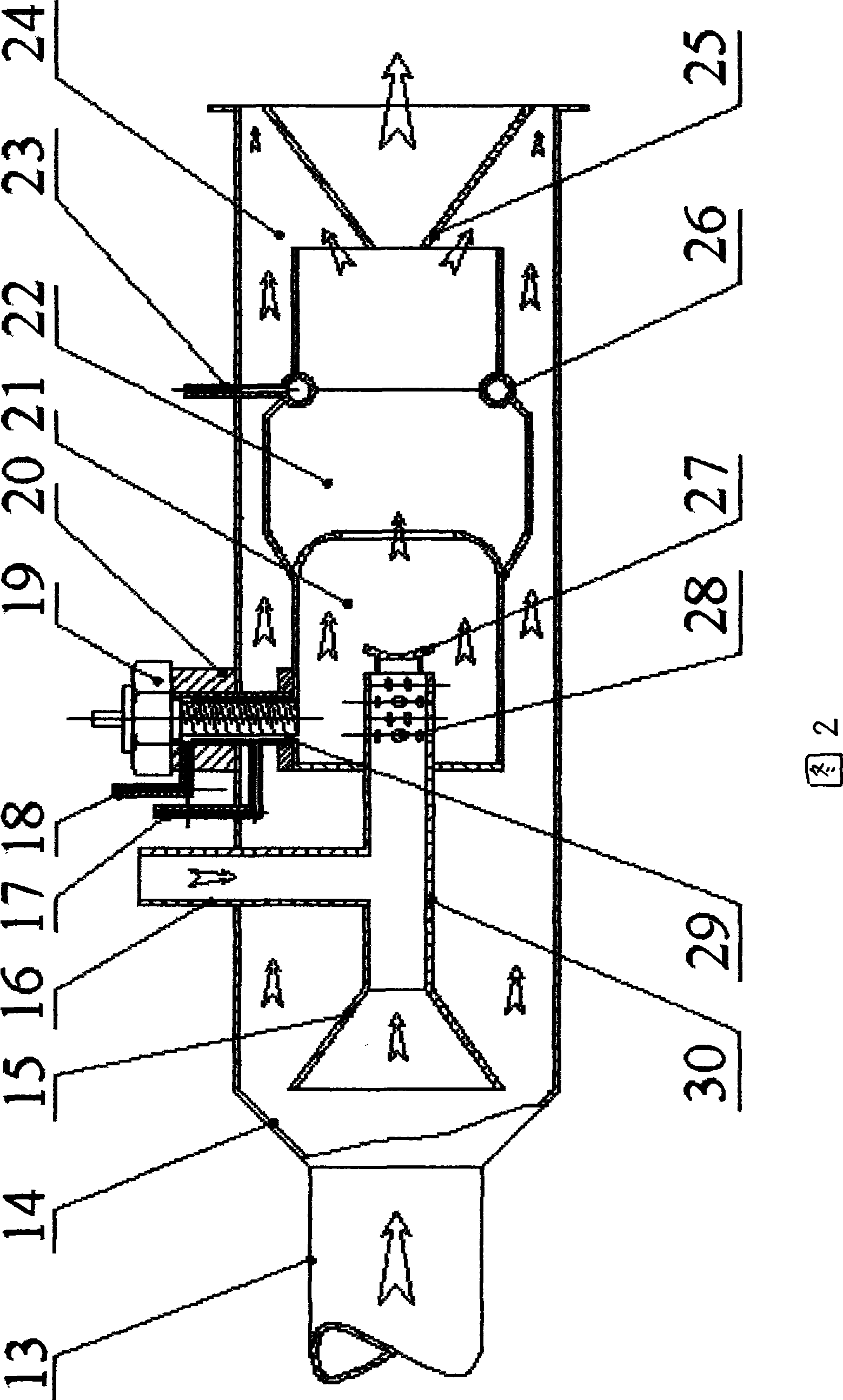
[0057] Fuel System

[0058] Part of the fuel is taken from the engine oil return line, and the fuel enters the burner through the fuel meter under the action of the pressure regulating valve. Part of it enters the burner evaporation chamber for primary combustion, and the other part enters the exhaust interlayer for tertiary combustion.

[0059] intake system

[0060] The burner intake system mainly includes three parts: one is that the air pump provides a small amount of fresh air for ignition; the other is that the turbocharger provides fresh air for combustion under certain working conditions; Exhaust is used for combustion.

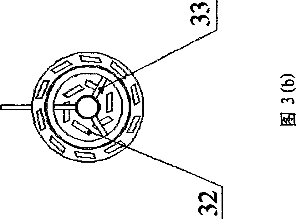
[0061] ignition device

[0062] After the glow plug is energized to preheat the fuel adsorption network, the fuel enters the evaporation chamber and evaporates on the surface of the adsorption network and is ignited by the glow plug. The micro air pump can effectively improve the ignition reliability and avoid the carbon deposition problem of the ...


PUM


Abstract

The invention relates to a device, a system and a method for exhausting and heating under all operating conditions of a diesel engine, and belongs to the technical field of pollution control of tail gas particle. The heating device comprises a first-stage combustion chamber, a second-stage combustion chamber and a third-stage combustion chamber orderly connected in series with a shell, a whirlpool groove, a tapered spoiler, a spoiler groove, a triangular support of the tapered spoiler, a first-stage combustion oil supply pipe, a circular fuel oil evaporating pipe, a third-stage combustion oil supply pipe, an air intake guide cylinder, a fresh air guide cylinder, an exhaust tapered air inlet, an air inlet and an air intake baffle. An electronic control unit judges whether to regenerate by monitoring exhaust temperature and pressure at two ends of a particle catcher; when regeneration is needed, oxygen content in the exhausted air is judged, and when the oxygen content is lower than a preset value, an air pump is controlled to provide little air so as to reliably ignite under all operating conditions. The device, the system and the method have the advantages of low energy consumption, simple operation method, high combustion efficiency and reliable operation, and can work under all the operating conditions of an engine.

Description

[0001] The invention belongs to the technical field of diesel engine tail gas particulate pollution control, and further relates to a device, system and method for heating exhaust gas of a diesel engine under all working conditions. Background technique [0002] Diesel engines have been widely used in various industries all over the world due to their high thermal efficiency and low exhaust emissions, but their high particulate emissions have always been a problem that plagues people. A particulate filter (DPF) is an effective method of controlling diesel particulates. Although the trapping efficiency of the current trap can reach more than 90%, the removal of particles after trapping (that is, the regeneration of the trap) is the main reason restricting the application of the trap. [0003] Thermal regeneration is a more commonly used regeneration method for particulate traps. Increase the exhaust gas temperature by heating or directly selectively heat the particles to burn ...

Claims


Application Information

Patent Timeline
IPC IPC(8): F01N3/023F01N9/00
CPCY02T10/47Y02T10/40
Inventor 资新运姚广涛张春润徐正飞姜大海邓成林赵传利
Owner MILITARY TRANSPORTATION UNIV PLA
Why Eureka
Try Eureka