Energy-saving control method and system for heat exchange station

A technology of energy-saving control and heat exchange station, which is applied in the direction of heating system, heating method, space heating and ventilation details, etc. It can solve the problems of not meeting the needs of heating users, the large heat demand of the heating system, and the impact of heat exchange station operation efficiency, etc. problems, to achieve the effect of improving energy saving and cost saving benefits, precise energy saving control, and refined control methods

Active Publication Date: 2021-12-31
TSINGHUA UNIV
View PDF6 Cites 0 Cited by
  • Summary
  • Abstract
  • Description
  • Claims
  • Application Information

AI Technical Summary

Problems solved by technology

[0005] Therefore, the energy saving and emission reduction of the heat exchange station involves two levels: one is whether the heat exchanged between the primary pipe network and the secondary pipe network is reasonable, that is, insufficient heat exchange will lead to failure to meet the needs of heating users, while the heat exchange If it is too large, it will cause waste of heat; the second is how to save energy under the premise of ensuring the needs of heating users, especially how to make the circulating pump unit operate in the highest efficiency area, which can not only ensure energy saving effect but also keep the pump unit in a good operating state, prolong equipment lifespan
[0006] However, in the existing technologies related to energy saving of heat exchange stations, few people fully consider the optimization and control of these two levels of energy conservation. The heat demand is the largest at night, and the different electricity prices in peak and valley also have a major impact on the operating efficiency of the heat exchange station

Method used


Image

  • Energy-saving control method and system for heat exchange station
  • Energy-saving control method and system for heat exchange station
  • Energy-saving control method and system for heat exchange station

Examples


Embodiment Construction

[0063] Specific embodiments of the present invention will be described in detail below in conjunction with the accompanying drawings.

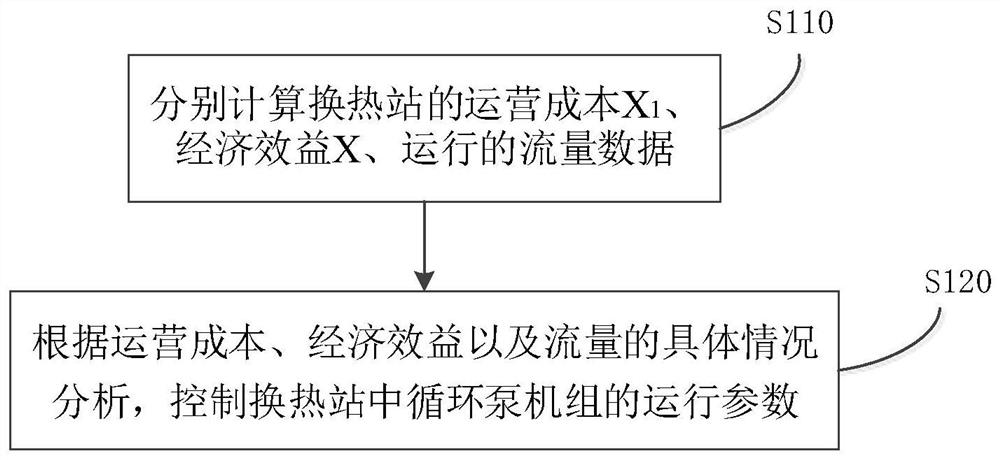
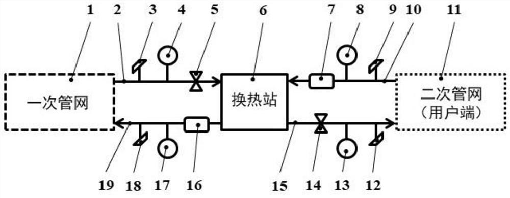
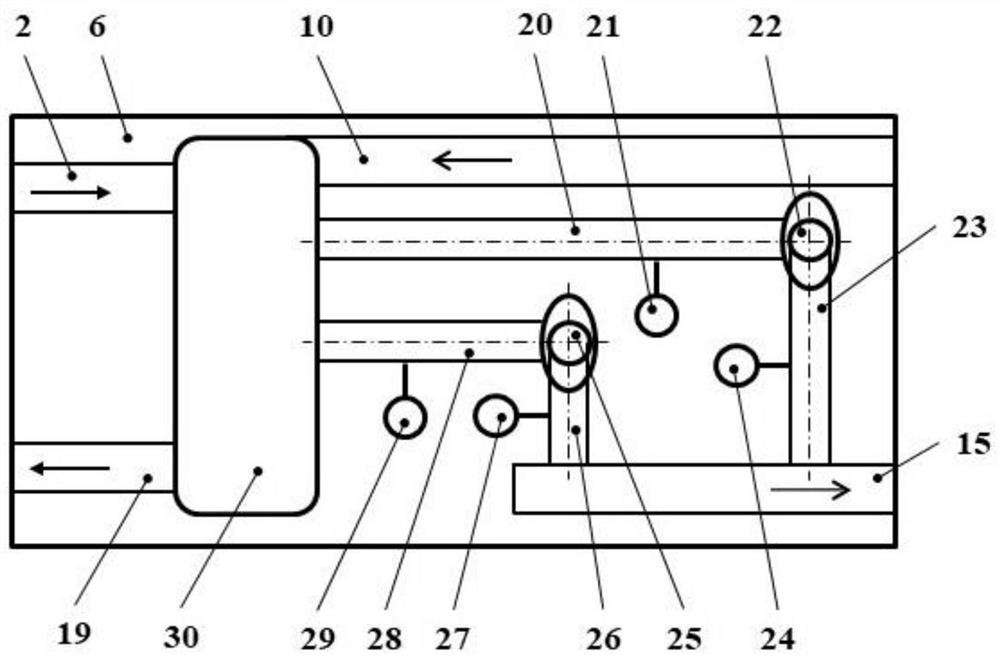
[0064] figure 1 A flow chart showing a method for energy-saving control of a heat exchange station according to the present invention; figure 2 It shows the connection relationship between the heat exchange station and the pipe network system according to the present invention; image 3 shows the layout of the interior of the heat exchange station; Figure 4 shows a schematic diagram of the operating conditions of the jth pump unit in the heat exchange station; and, Figure 5 It shows a schematic diagram of the variable speed parallel operation condition of the j1th pump unit and the j2th pump unit in the heat exchange station.

[0065] An energy-saving control method and system for a heat exchange station, relating to an operation control method and connection system for a heat exchange station and a circulating pump unit that realize hea...


PUM


Abstract

The invention provides an energy-saving control method and system for a heat exchange station. The energy-saving control method comprises the following step that the operation cost X1, the economic benefit X and operation flow data of the heat exchange station are calculated respectively, wherein operation parameters of a circulating pump unit are controlled through the operation cost X1, the economic benefit X and the operation flow of the heat exchange station. By means of the energy-saving control method and system, according to thermodynamic parameters of a primary pipe network and the heat supply requirement of a secondary pipe network of a heating and heat supply system, the peak-valley electricity price factor is considered, the heat exchange flow of the primary pipe network and the secondary pipe network in the heat exchange station is controlled, and operating parameters of the circulating pump unit are controlled, so that the optimal energy-saving effect of saving heat energy and electric energy is achieved.

Description

technical field [0001] The invention relates to the technical field of heat supply engineering, and more specifically, to an energy-saving control method for a heat exchange station and an energy-saving control system for a heat exchange station implementing the energy-saving control method for a heat exchange station. Background technique [0002] The heat exchange station is the key unit for heat exchange and liquid pressurization in the heating or heating pipe network system. Its operation quality not only determines the heating quality of the user end, but also relates to the energy saving and emission reduction of the whole society and the saving of heating enterprises. synergy. [0003] At present, in most heating systems, traditional methods are often used to estimate the heat exchange capacity of heat exchange stations, and measures such as throttle valves are used to control the operating conditions of circulating pump units in heat exchange stations. This will inev...

Claims


Application Information

Patent Timeline
Patent Type & Authority Applications(China)
IPC IPC(8): F24D19/10F24D19/00
CPCF24D19/1009F24D19/0002
Inventor 罗先武叶维祥
Owner TSINGHUA UNIV
Why Eureka
Try Eureka