A method and device for calculating obstacle heading angle based on time synchronization

A technology of time synchronization and heading angle, applied in two-dimensional position/channel control, transportation and packaging, vehicle position/route/altitude control, etc., can solve the problems of unguaranteed stability, difficult and difficult accuracy of results, etc.

Active Publication Date: 2022-04-12
ZHIDAO NETWORK TECH (BEIJING) CO LTD
View PDF13 Cites 0 Cited by
  • Summary
  • Abstract
  • Description
  • Claims
  • Application Information

AI Technical Summary

Problems solved by technology

[0004] First of all, in the perceptual detection algorithm, it is difficult to calculate the yaw angle of obstacles using image perception, and the results are difficult to be accurate; it is not easy to calculate the yaw angle of obstacles accurately by using traditional point cloud clustering algorithms, and the stability cannot be guaranteed.
Secondly, the calculation of the obstacle heading angle also involves the own vehicle heading angle output by the own vehicle inertial navigation, the calibration results of the inertial navigation and perception sensors, and the time synchronization of the sensors, which is a systematic issue involving software, hardware and algorithms.
[0005] For the above problems, no effective solution has been proposed

Method used


Image

  • A method and device for calculating obstacle heading angle based on time synchronization
  • A method and device for calculating obstacle heading angle based on time synchronization
  • A method and device for calculating obstacle heading angle based on time synchronization

Examples


Embodiment 1

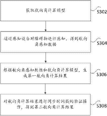
[0027] image 3 is a flow chart of a time synchronization-based obstacle heading angle calculation method according to an embodiment of the present invention, such as image 3 As shown, the method includes the following steps:

[0028] Step S302, obtaining a heading angle calculation model, wherein the heading angle calculation model is obtained through training on the heading angle yaw value historical data.

[0029] Optionally, the heading angle calculation model adopts a double-chain layer DNN network model.

[0030] Specifically, in order to solve the perceptual detection algorithm of the prior art, it is difficult to calculate the yaw angle of obstacles using image perception, and the results are also difficult to be accurate; it is not easy to calculate the yaw angle of obstacles using traditional point cloud clustering algorithms Accuracy and stability cannot be guaranteed. Secondly, the calculation of the obstacle heading angle also involves the own vehicle heading ...

Embodiment 2

[0042] Figure 4 is a structural block diagram of a time synchronization-based obstacle course angle calculation device according to an embodiment of the present invention, such as Figure 4 As shown, the method includes the following steps:

[0043] The acquisition module 40 is configured to acquire a heading angle calculation model, wherein the heading angle calculation model is obtained through training on the course angle yaw value historical data.

[0044] Optionally, the heading angle calculation model adopts a double-chain layer DNN network model.

[0045] Specifically, in order to solve the perceptual detection algorithm of the prior art, it is difficult to calculate the yaw angle of obstacles using image perception, and the results are also difficult to be accurate; it is not easy to calculate the yaw angle of obstacles using traditional point cloud clustering algorithms Accuracy and stability cannot be guaranteed. Secondly, the calculation of the obstacle heading ...


PUM


Abstract

The invention discloses a method and device for calculating the course angle of an obstacle based on time synchronization. Wherein, the method includes: obtaining a heading angle calculation model, wherein the heading angle calculation model is obtained by training the historical data of the heading angle yaw value; sensing obstacles through a sensing device to obtain heading angle perception data; according to the heading angle The angle perception data and the heading angle calculation model are used to generate a first heading angle calculation result; and the verification operation of the synchronization time stamp is performed on the heading angle calculation result to obtain a second heading angle calculation result. The invention solves the problem that in the perception detection algorithm of the prior art, it is difficult to calculate the yaw angle of obstacles using image perception, and the result is also difficult to be accurate; it is not easy to calculate the yaw angle of obstacles accurately by using the traditional point cloud clustering algorithm , and stability cannot be guaranteed. Secondly, the calculation of the obstacle heading angle also involves the own vehicle heading angle output by the inertial navigation of the own vehicle, the calibration results of the inertial navigation and perception sensors, and the time synchronization of the sensors, which is a technical problem involving systematic problems of software, hardware and algorithms. .

Description

technical field [0001] The present invention relates to the field of intelligent driving, in particular to a method and device for calculating an obstacle heading angle based on time synchronization. Background technique [0002] With the continuous development of intelligent technology, more and more intelligent devices are used in people's life, work and study. The use of intelligent technology has improved the quality of people's life and increased the efficiency of people's study and work. [0003] At present, in the field of automatic driving, automatic intelligent driving using multi-directional perception is the mainstream driving design concept, but in the field of intelligent driving in the existing technology, although the calculation of the heading angle of the vehicle is an important calculation of the driving force of the automatic driving of the vehicle parameters, but in the unmanned driving perception system, the heading angle of obstacles is usually not accu...

Claims


Application Information

Patent Timeline
Patent Type & Authority Patents(China)
IPC IPC(8): G05D1/02
CPCG05D1/0257G05D2201/0212
Inventor 孙亚飞胡铮铭胡孟孟张海强李成军
Owner ZHIDAO NETWORK TECH (BEIJING) CO LTD
Why Eureka
Try Eureka