Multi-angle detection jig
A technology for detecting fixtures and multi-angles, which is applied in the field of fixtures and can solve problems such as the inability to realize multi-angle detection of camera modules
- Summary
- Abstract
- Description
- Claims
- Application Information
AI Technical Summary
Problems solved by technology
Method used
Image

Examples
Embodiment 1
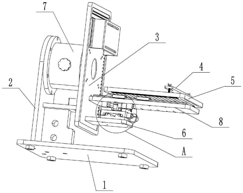
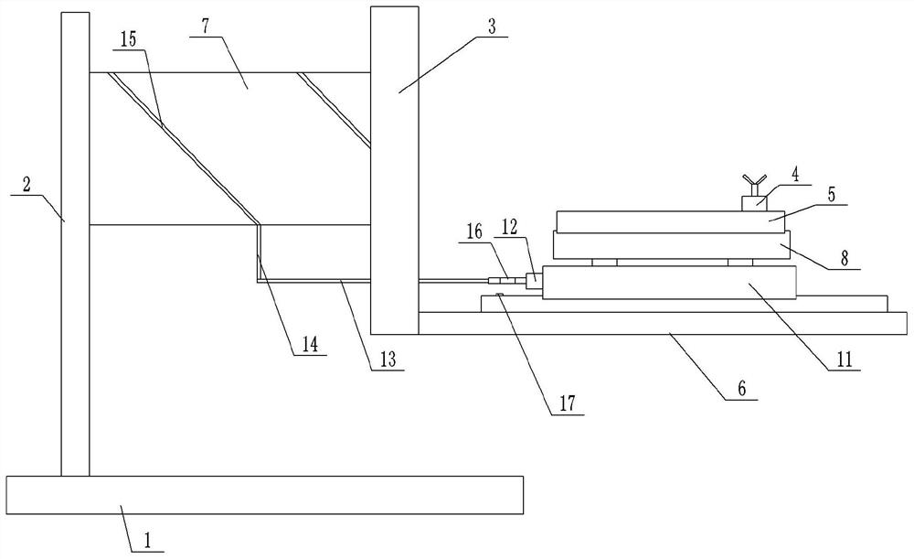
[0024] Basic as attached Figure 1-Figure 2 Shown: a multi-angle detection fixture, including a frame 1, a support plate 2, a back plate 3, a fixture base 5 and a fixture bead 4, and the bottom end of the support plate 2 is vertically welded and fixedly connected to the frame 1, the jig base 5 is installed on the back plate 3, the jig bead 4 is located above the jig base 5, and a compression bolt is connected between the end of the jig bead 4 and the jig base 5. The back plate 3 is connected with the support plate 2 in rotation, and the specific rotation method is: a fixed shaft 7 is welded on the right side of the support plate 2, and a bearing is connected between the right end of the fixed shaft 7 and the back plate 3. The back plate 3 and the supporting plate 2 are arranged in parallel.
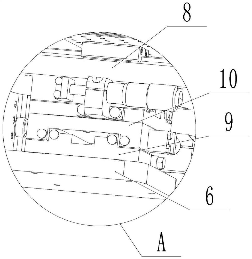
[0025] The right side of the bottom of the back plate 3 is welded and fixedly connected with a fixed plate 6, and the bottom of the jig base 5 is fixedly connected with a movable plate 8...
Embodiment 2
[0028] In addition to detecting the travel of the camera module in Embodiment 1, in combination with Figure 5 As shown, the first detection point 21 and the second detection point 22 are respectively provided on the two sides of the camera module 19, and the first detection point 21 and the second detection point 22 are not in the same vertical plane. When detecting, The detection device also needs to detect the first detection point 21 and the second detection point 22 respectively. Since the detection device does not move, after the camera module 19 is rotated in this solution, the moving plate 8 needs to be moved in the X direction, so that the camera module moves in the X direction, so that the first detection point 21 and the second detection point 21 can be detected. All the points 22 can be opposite to the detection device, so that the detection device can detect the first detection point 21 and the second detection point 22 . Because the moving plate 8 is manually pr...
PUM
 Abstract
Description
Claims
Application Information
 - R&D
- Intellectual Property
- Life Sciences
- Materials
- Tech Scout
- Unparalleled Data Quality
- Higher Quality Content
- 60% Fewer Hallucinations
Browse by: Latest US Patents, China's latest patents, Technical Efficacy Thesaurus, Application Domain, Technology Topic, Popular Technical Reports.
© 2025 PatSnap. All rights reserved.Legal|Privacy policy|Modern Slavery Act Transparency Statement|Sitemap|About US| Contact US: help@patsnap.com