Gas treatment device

A gas treatment and gas technology, applied in the separation of dispersed particles, chemical instruments and methods, separation methods, etc., can solve the problems of unsatisfactory defogging effect and large flow resistance of airflow

Pending Publication Date: 2022-01-04
AIER WEICHEN TECH BEIJING CO LTD
View PDF0 Cites 0 Cited by
  • Summary
  • Abstract
  • Description
  • Claims
  • Application Information

AI Technical Summary

Problems solved by technology

In the prior art, a demister with fixed blades is used for swirl defogging. In this way, th

Method used


Image

  • Gas treatment device
  • Gas treatment device
  • Gas treatment device

Examples


Embodiment Construction

[0039] Exemplary embodiments of the present disclosure will be described in more detail below with reference to the accompanying drawings. Although exemplary embodiments of the present disclosure are shown in the drawings, it should be understood that the present disclosure may be embodied in various forms and should not be limited by the embodiments set forth herein. Rather, these embodiments are provided for more thorough understanding of the present disclosure and to fully convey the scope of the present disclosure to those skilled in the art.

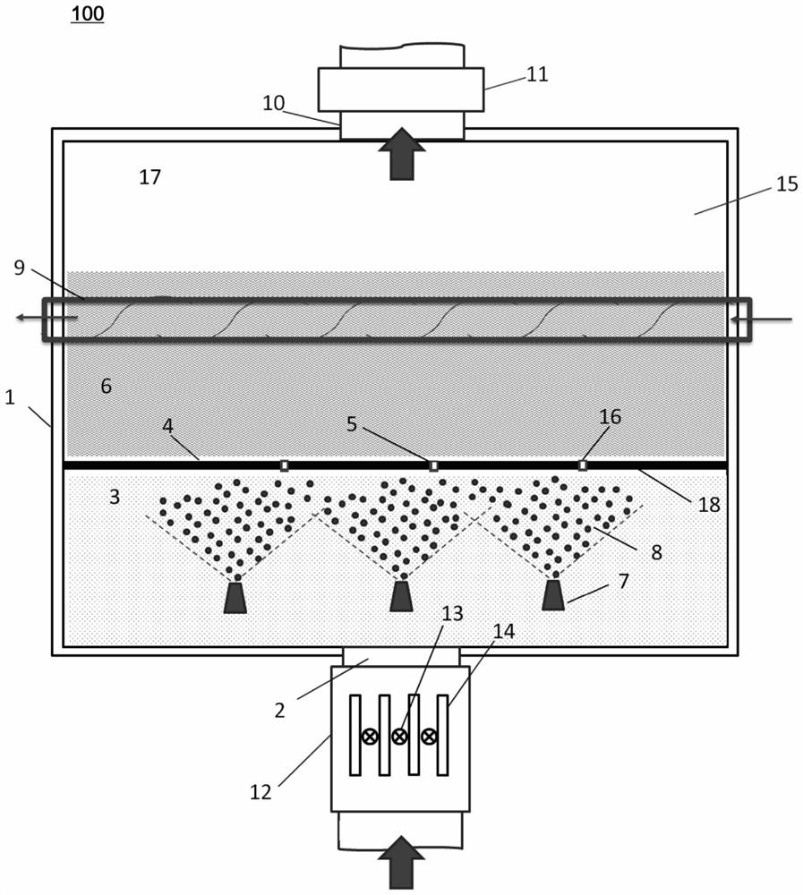
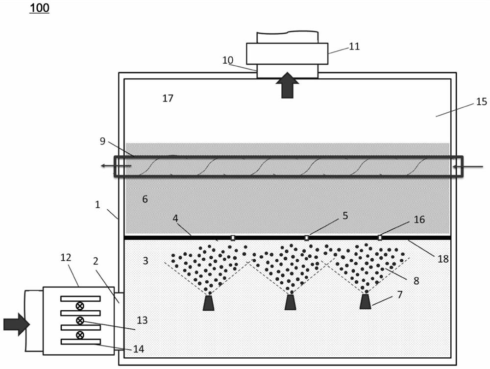
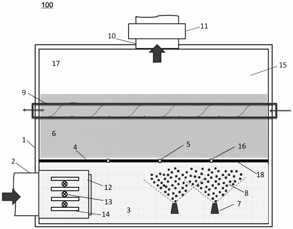
[0040] In order to solve the above technical problems, the present invention provides a gas treatment device. figure 1 A schematic structural diagram of a gas processing device 100 according to an embodiment of the present invention is shown. figure 2 A schematic structural diagram of a gas processing device 100 according to another embodiment of the present invention is shown. image 3 A schematic structural diagram of a gas pro...


PUM


Abstract

The invention provides a gas treatment device. The gas treatment device comprises: a shell, which surrounds a cavity; a gas inlet, which is formed in the shell and is configured to allow gas to enter the cavity through the gas inlet; an outlet, which is formed in the shell and is configured to allow the gas entering the cavity to be discharged from the outlet; a partition plate, which is arranged in the cavity to divide the cavity into a first area communicating with the gas inlet and a second area communicating with the outlet; and a nozzle, which is arranged in the first region and configured to spray a first liquid toward the partition plate, wherein the partition plate comprises a through hole, and the through hole is configured to allow the gas entering the cavity from the gas inlet and the sprayed first liquid to enter the second area from the first area through the through hole so as to treat the gas. The device further comprises a demister arranged at the outlet, wherein the demister is provided with rotatable blades, and liquid drops carried in gas exhausted from the outlet are removed through the rotatable blades. According to the above scheme, the gas treatment device has the advantages of small airflow flowing resistance and good demisting effect.

Description

technical field [0001] The invention relates to the technical field of gas treatment, in particular to a gas treatment device. Background technique [0002] The increase in energy demand caused by economic growth has led to the generation of air pollutants, and the governance problems in many fields (such as thermal power, steel, chemical industry, etc.) have become increasingly prominent. Therefore, the demand for gas treatment technology is also increasing. In order to improve the treatment effect of gas (such as polluted gas), the gas is treated by mixing the gas with the sprayed treatment liquid and then dispersing or bubbling through the through holes of the partition plate. After the gas is processed, liquid droplets will be carried in the discharged gas, and the discharged gas needs to be defogged to remove the carried liquid droplets. In the prior art, a demister with fixed blades is used for swirl demisting, but in this way, the flow resistance of the airflow is re...

Claims


Application Information

Patent Timeline
IPC IPC(8): B01D53/00B01D53/14B01D53/18B01D53/32B01D53/44B01D53/76
CPCB01D53/32B01D53/00B01D53/18B01D53/1487B01D53/76B01D53/44
Inventor 王昊
Owner AIER WEICHEN TECH BEIJING CO LTD
Why Eureka
Try Eureka