Air purification system for vehicles

A technology for air purification equipment and vehicles, applied in air conditioning systems, vehicle parts, air treatment equipment, etc., can solve the problems of long residence time, small reaction surface, incomplete reaction, etc., and achieve high-efficiency purification ability and high-efficiency photocatalysis effect

Active Publication Date: 2011-11-23
ADIENT LUXEMBOURG HLDG SARL
View PDF6 Cites 0 Cited by
  • Summary
  • Abstract
  • Description
  • Claims
  • Application Information

AI Technical Summary

Problems solved by technology

[0004] A disadvantage of the known photocatalytic air purification methods is their inefficiency, in particular due to the small reaction surface in the reaction

Method used


Image

  • Air purification system for vehicles
  • Air purification system for vehicles
  • Air purification system for vehicles

Examples


Embodiment Construction

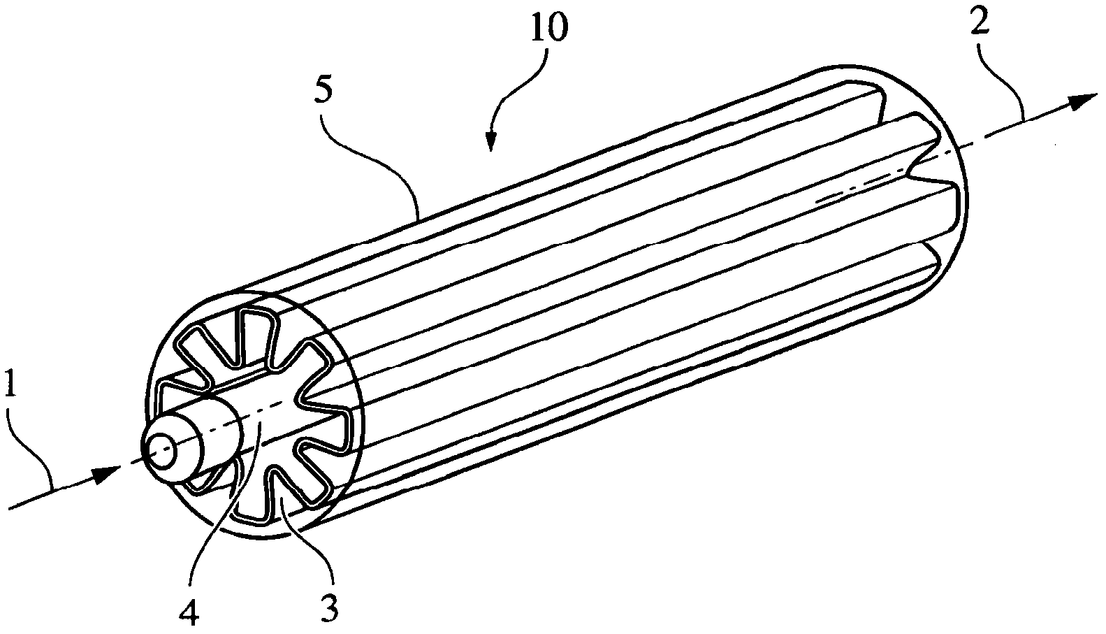
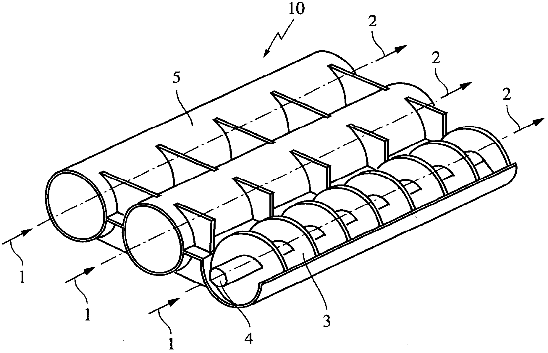
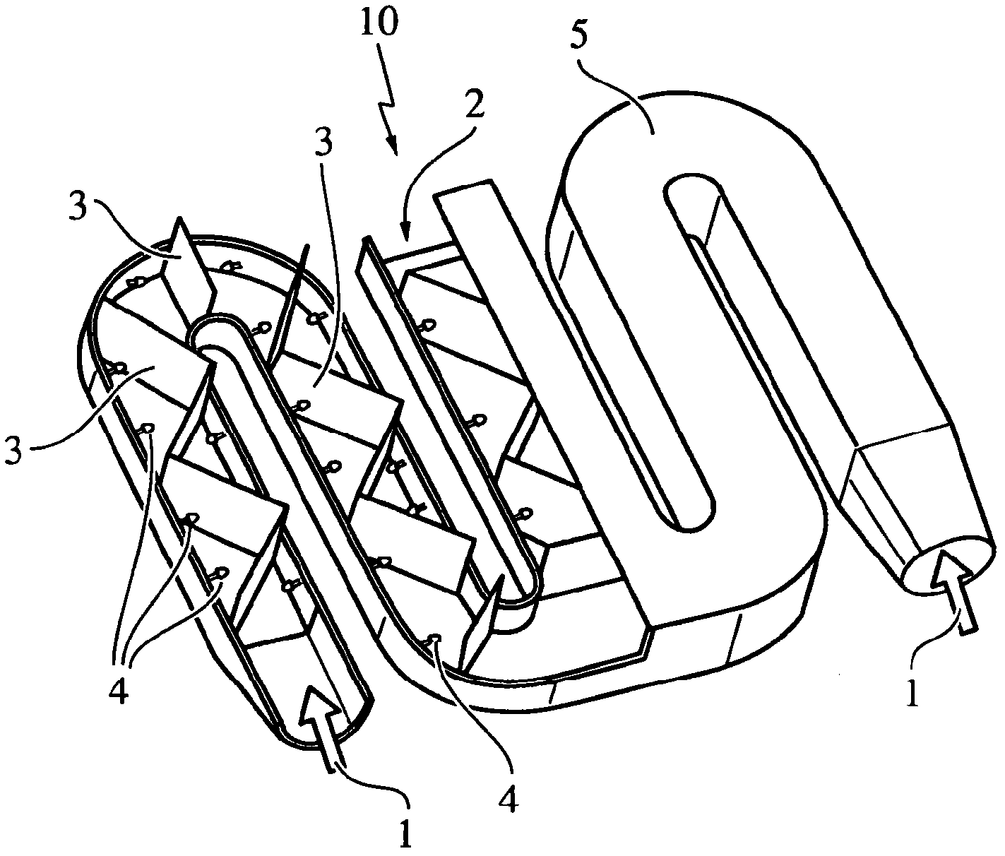
[0031] In all the illustrated embodiments, the air purification device 10 or the air purification system 10 includes an air inlet 1 and an air outlet 2. In addition, the air purification device 10 or the air purification system 10 has a housing 5, a light source 4 or multiple light sources 4, and a reaction surface element 3 or a plurality of reaction surface elements 3. In the first to fifth illustrated embodiments, in particular a grid or wire mesh provided with a catalytic material (as a surface coating) is provided as the reaction surface element 3. The catalytic material is especially designed as a titanium dioxide material or a material comprising titanium dioxide, for example as a nanostructured catalytic material (nano-titanium dioxide). In the first to tenth illustrated embodiments, the light source 4 is set in the form of a light source 4 that generates ultraviolet radiation (UV radiation), especially a light source 4 that generates UV-A radiation, especially in the f...


PUM


Abstract

An air purification system is proposed, in particular for a vehicle, having an air inlet (1), an air outlet (2) and an air conduction volume between the air inlet and the air outlet, wherein at least one reaction surface element (3) is provided in the air conduction volume, at least one light source (4) for ultraviolet light being arranged in the air conduction volume and the reaction surface element being arranged substantially in the entire air conduction volume.

Description

Technical field [0001] The present invention relates to an air purification system, in particular to an air purification system for vehicles or airplanes or other vehicles. Background technique [0002] Especially for the interior of a vehicle, it is very important to generate clean air, especially air that is basically free of pathogens and does not contain organic pollutants, especially to ensure the health of the vehicle occupants, thereby also ensuring a high level of safety of the vehicle. Therefore, purifying the air inside the vehicle cheaply and effectively has great economic benefits, especially by using a device that is compact, can be produced at a low cost, and can operate with relatively low energy consumption. Known equipment for purifying air includes ozone generators, filtration systems, air ionizers (Luftionisator) and the like. In principle, the filter system is only suitable for separating relatively large particulate air components (dust, pollen, microorganis...

Claims


Application Information

Patent Timeline
IPC IPC(8): B60H3/00A61L9/20F24F3/16
CPCB60H3/0078F24F3/166F24F2003/1667B60H2003/0675A61L9/205F24F8/22F24F8/192Y02A50/20A61L9/20B01J35/02B60H3/0071B60H3/0085
Inventor B·格罗斯H-G·维尔纳J·赫斯特伯格梁文龙
Owner ADIENT LUXEMBOURG HLDG SARL
Why Eureka
Try Eureka