

New wind machine
A technology for fresh air fans and blowers, which is applied in ventilation systems, mechanical equipment, machines/engines, etc. It can solve problems affecting user experience, decreased air volume of fresh air fans, increased noise, etc., and achieves compact structure, reduced working noise, and increased The effect of large exhaust air volume
- Summary
- Abstract
- Description
- Claims
- Application Information
AI Technical Summary
Problems solved by technology
Method used
Image

Examples
Embodiment Construction
[0058] Embodiments of the present invention are described in detail below, examples of which are shown in the drawings, wherein the same or similar reference numerals designate the same or similar elements or elements having the same or similar functions throughout. The embodiments described below by referring to the figures are exemplary only for explaining the present invention and should not be construed as limiting the present invention.
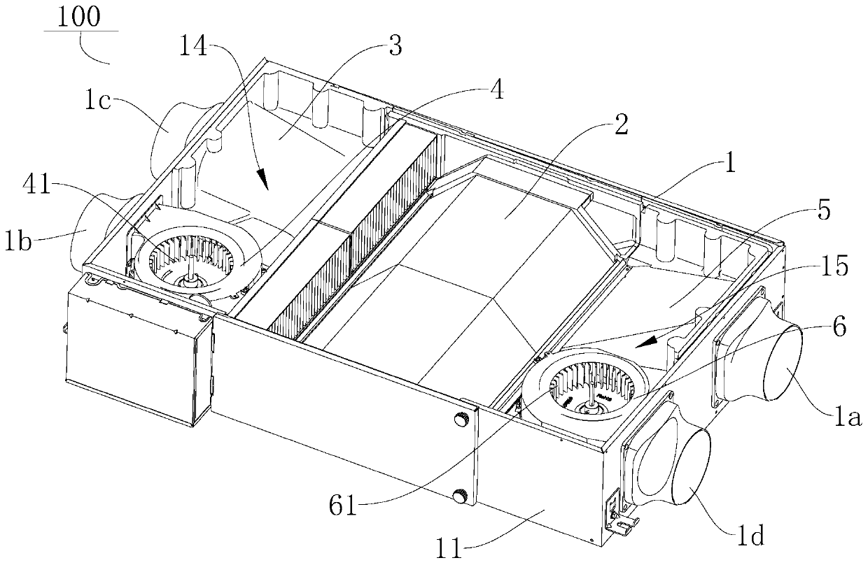
[0059] Refer below Figure 1-Figure 13 The fresh air machine 100 according to the embodiment of the present invention is described, and the fresh air machine 100 can introduce fresh air into an indoor environment.
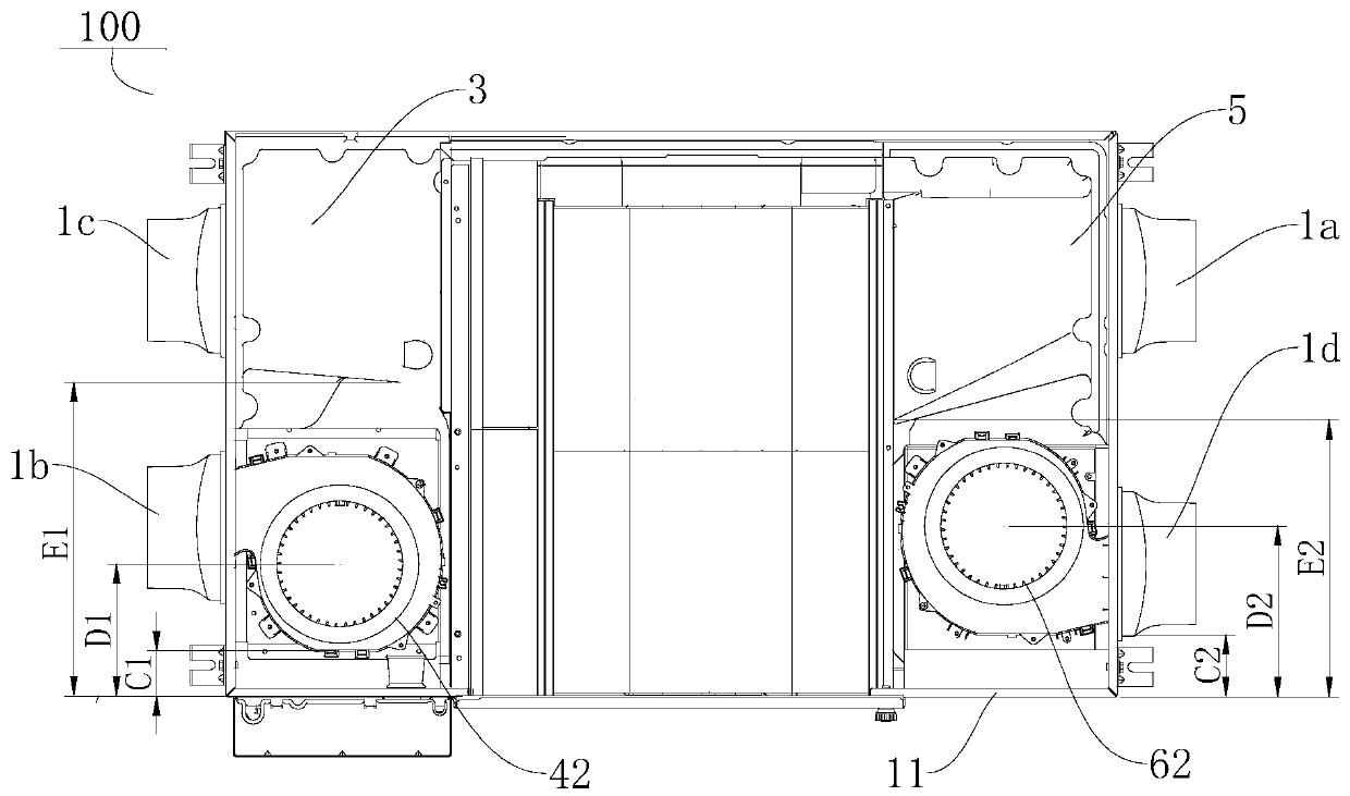
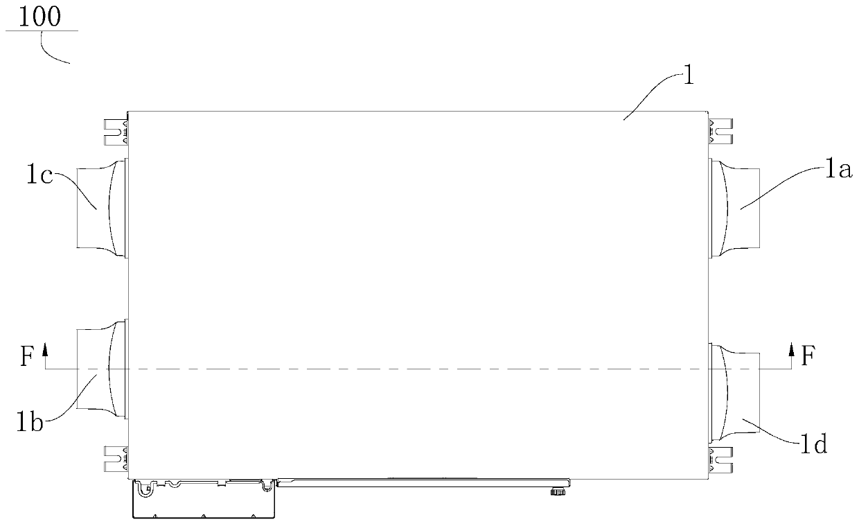
[0060] refer to figure 1 and figure 2 As shown, the fresh air blower 100 according to the embodiment of the present invention may include a housing 1, a heat exchange core 2, a first air duct 3 and a first fan assembly 4, and the heat exchange core 2, the first air duct 3 and the second air duct A fan assembly 4 is provid...
PUM
 Abstract
Description
Claims
Application Information