Wiring bending device with cable arrangement function for communication cables

A communication cable and bending device technology, which is applied in the field of communication, can solve the problems of inconvenient communication cable wiring bending, communication cable crossing, etc., and achieve the effect of neat arrangement and easy arrangement

Pending Publication Date: 2022-01-04
邓福河
View PDF0 Cites 0 Cited by
  • Summary
  • Abstract
  • Description
  • Claims
  • Application Information

AI Technical Summary

Problems solved by technology

[0004] Based on this, it is necessary to address the above problems, and propose a wiring bending device for communication cables that can automatically bend communication cables of different quantities and thicknesses and automatically arrange communication cables. , to solve the problem that the existing technology proposed in the above-mentioned background technology is inconvenient to bend a large number of communication cables, and the phenomenon that communication cables cross easily occurs

Method used


Image

  • Wiring bending device with cable arrangement function for communication cables
  • Wiring bending device with cable arrangement function for communication cables
  • Wiring bending device with cable arrangement function for communication cables

Examples


Embodiment 1

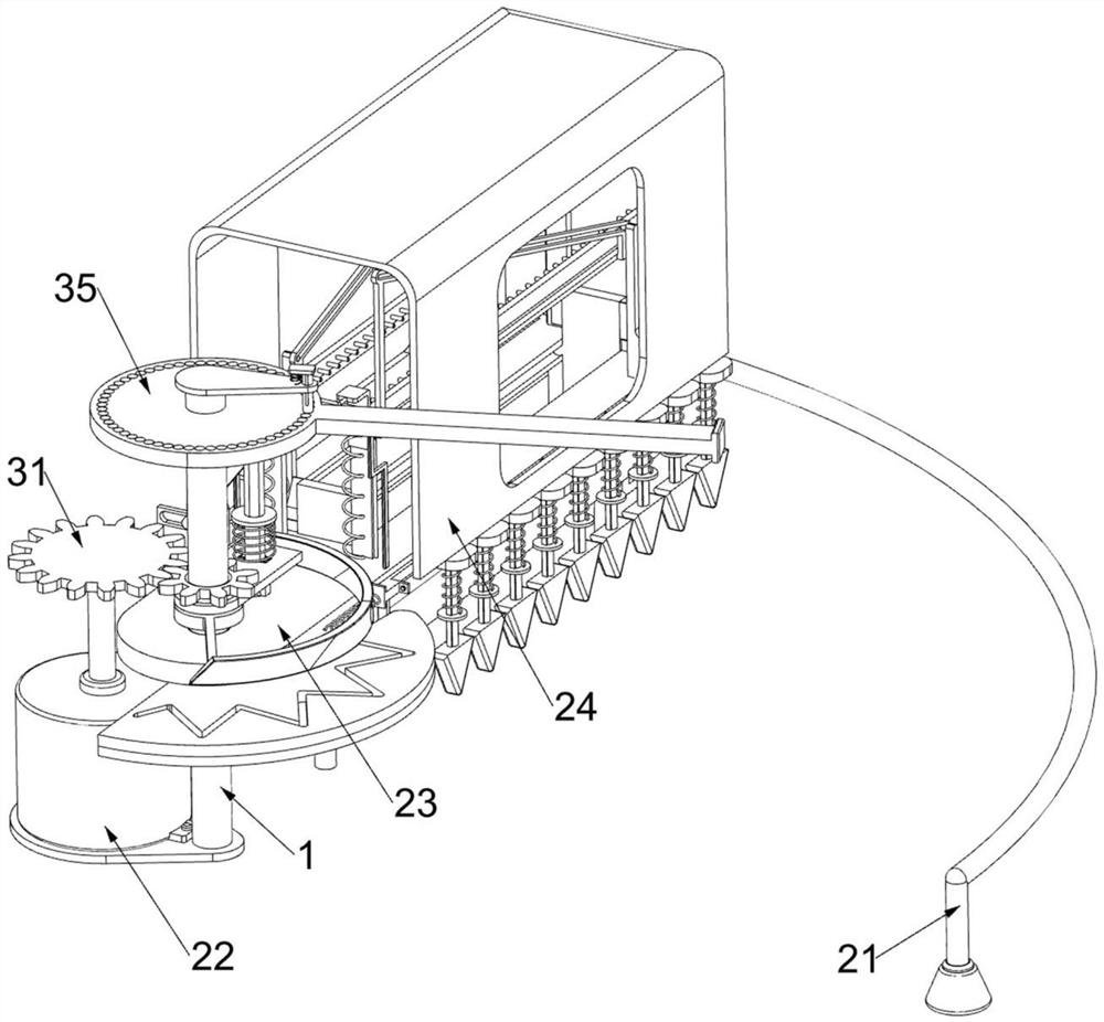
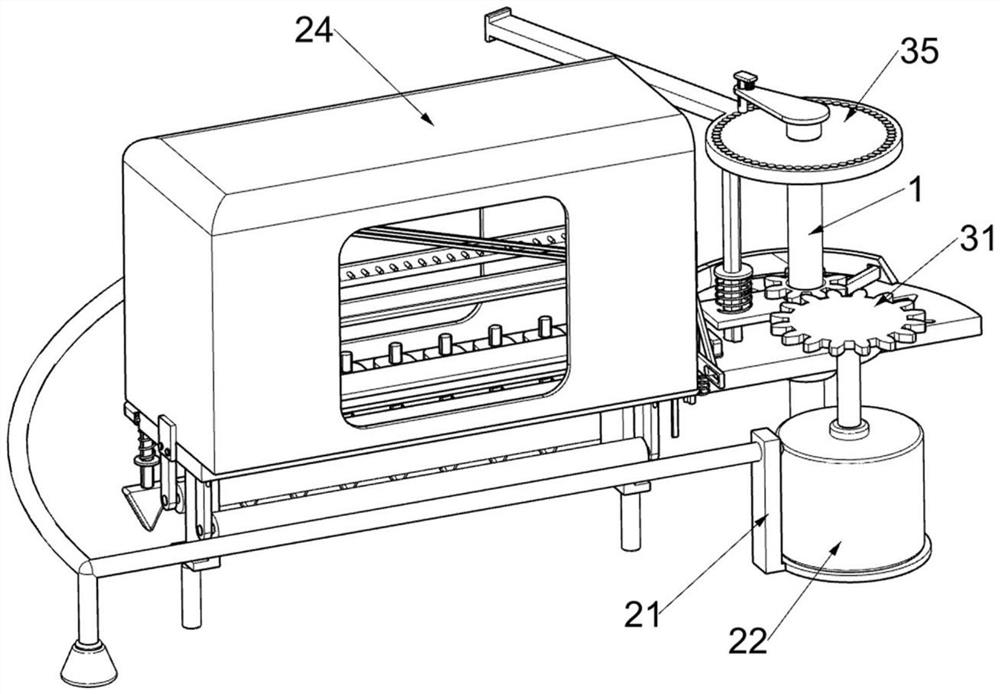
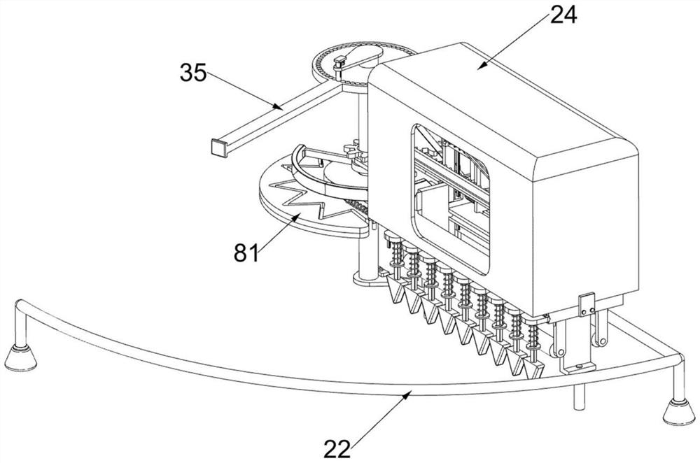
[0044] A wiring bending device with cable arrangement function for communication cables, such as Figure 1-8 As shown, it includes a fixed support frame 1, a special-shaped support frame 21, a motor 22, a rotating support frame 23, a protective frame 24, a rotating assembly 3 and a limit assembly 4, and the fixed support frame 1 is fixedly connected with a special-shaped support frame 21. The support frame 21 is U-shaped, and the motor 22 for driving is fixedly installed on the top of the fixed support frame 1. The fixed support frame 1 is rotatably connected with a rotating support frame 23, and the rotating support frame 23 is connected with a protective frame 24 by bolts. The frame 1 is provided with a rotating assembly 3 for bending the communication cables, and the rotating support frame 23 is provided with a limiting assembly 4 for restricting the communication cables.

[0045] The rotating assembly 3 includes a first spur gear 31, a rotating support plate 311, a second ...

Embodiment 2

[0049] On the basis of Example 1, such as Figure 8-9 As shown, an adjustment assembly 5 is also included. The adjustment assembly 5 for adjusting the bending angle is arranged on the fixed support frame 1. The adjustment assembly 5 includes a fixed support plate 51, a limit frame 52 and a second spring 53. The top of the frame 1 is fixedly connected with a fixed support plate 51, and the fixed support plate 51 is slidably connected with a limit frame 52 for clamping the slotted adjustment frame 35, and the limit frame 52 is inserted into the slot of the slotted adjustment frame 35 A second spring 53 for driving the limit frame 52 to reset is connected between the limit frame 52 and the fixed support plate 51 .

[0050] Because there are a plurality of draw-in grooves at the bottom of the slotted adjustment frame 35, the slotted adjustment frame 35 can be manually rotated to adjust the angle of the slotted adjustment frame 35. By the cooperation of the limit frame 52 and the s...

Embodiment 3

[0052] On the basis of Example 2, such as Figure 10-13 As shown, it also includes a limit control assembly 6, the limit control assembly 6 is located on the fixed support frame 1, and the limit control assembly 6 includes an arc plate 61, an L-shaped clamp frame 62, a third spring 63, a sliding stop Plate frame 64, L-shaped support frame 65, swing dial frame 66, the first sliding card post frame 67 and the fourth spring 68, the fixed support frame 1 is fixedly connected with arc-shaped plate 61, and both sides of arc-shaped plate 61 are inclined planes Structure, on the second card column frame 45, be fixedly connected with L-shaped card column frame 62, be connected with the 3rd spring 63 that is used to drive L-shaped card column frame 62 resets between L-shaped card column frame 62 and rotating support frame 23, rotate The support frame 23 is slidably connected with a sliding baffle frame 64, the sliding baffle frame 64 is N-shaped, the sliding baffle frame 64 is in contac...


PUM


Abstract

The invention relates to the field of communication, in particular to a wiring bending device with a cable arrangement function for communication cables. The wiring bending device comprises a fixed support frame, a special-shaped support frame, a motor, a rotary support frame and the like. The special-shaped support frame is fixedly connected to the fixed support frame, the motor is fixedly installed on the top of the fixed support frame, and the rotary support frame is rotationally connected to the fixed support frame. A second sliding support frame and devices on the second sliding support frame can move in a reciprocating mode, a stirring frame can stir the communication cables which possibly intersect in order, the communication cables are convenient to arrange, the communication cables are arranged in order, therefore, the bent communication cables are more attractive, and the purpose that the communication cables can be automatically arranged is achieved.

Description

technical field [0001] The invention relates to the communication field, in particular to a wiring bending device for communication cables with a cable arrangement function. Background technique [0002] Communication cable is a general term for various wires that transmit electrical or optical signals. Communication cables are usually composed of a cable core, a sheath and a sheath. The cable core is a symmetrical or coaxial structure of a solid insulator. Sheath, and wrapped with steel wire armor, so that it has a very strong tensile strength and anti-damage performance of foreign objects. There are many uses for communication cables. Communication cables are mainly used for control installation, connection equipment, power transmission, etc. It is a common and indispensable thing in daily life. [0003] When installing communication cables, in order to ensure the beauty of the communication cables and improve space utilization, it is necessary to bend the communication c...

Claims


Application Information

Patent Timeline
Patent Type & Authority Applications(China)
IPC IPC(8): B29C53/02B29C53/80B29L11/00B29L31/34
CPCB29C53/02B29C53/80B29L2011/0075B29L2031/3462
Inventor 邓福河
Owner 邓福河
Why Eureka
Try Eureka