Gravure electronic engraving machine equipment built-in intelligent temperature control equipment

An electronic engraving, intelligent temperature control technology, applied in the field of engraving machines, can solve the problems of increasing equipment use limitations, easy to generate backflow, reducing heat dissipation efficiency, and temperature control work stability and accuracy, to suppress frequent startup and energy consumption. Consumption, Sustainability and Stability Improvements, Increased Multi-stage Processing Efficacy

Active Publication Date: 2022-06-24
深圳市国匠数控科技有限公司
View PDF8 Cites 0 Cited by
  • Summary
  • Abstract
  • Description
  • Claims
  • Application Information

AI Technical Summary

Problems solved by technology

[0003] The current electronic engraving machine will generate a lot of heat inside the body during the engraving process, which will cause the internal temperature of the body to rise, and excessive temperature will affect the normal operation of the components and increase the occurrence of component failures. Therefore A heat dissipation and temperature control mechanism is often needed to assist the engraving machine to work normally. The existing common heat dissipation mechanism often blows out the heat through the fan in the form of exhaust. However, the airflow alone cannot ensure the guidance of the heat source airflow, so it is easy to generate backflow. Reduce the heat dissipation efficiency and the stability and accuracy of temperature control work, and it is not easy for the temperature equipment to quickly make corresponding processing according to the temperature inside the body, resulting in the failure to maintain the constant temperature of the body, increasing the possibility of component heating failure and loss At the same time, in the gravure engraving process, more dust is prone to appear in the body, which is difficult to absorb and deal with, increasing the limitations of equipment use

Method used


Image

  • Gravure electronic engraving machine equipment built-in intelligent temperature control equipment
  • Gravure electronic engraving machine equipment built-in intelligent temperature control equipment
  • Gravure electronic engraving machine equipment built-in intelligent temperature control equipment

Examples


Embodiment 1

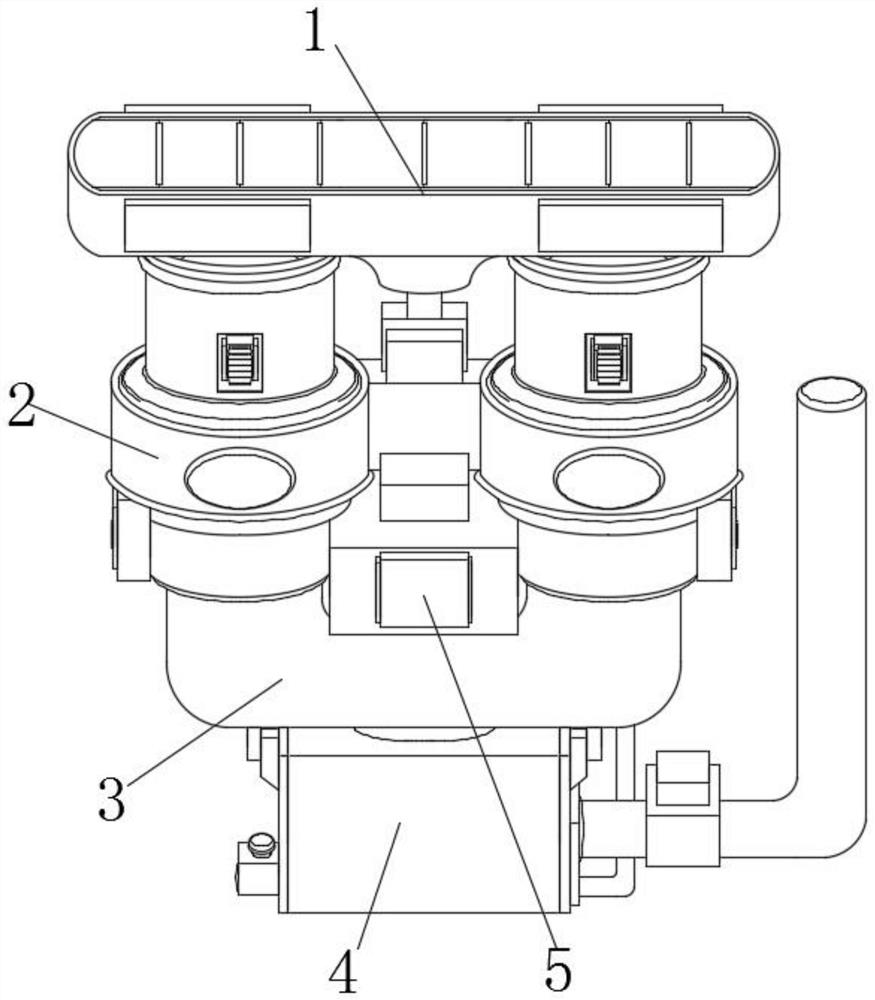
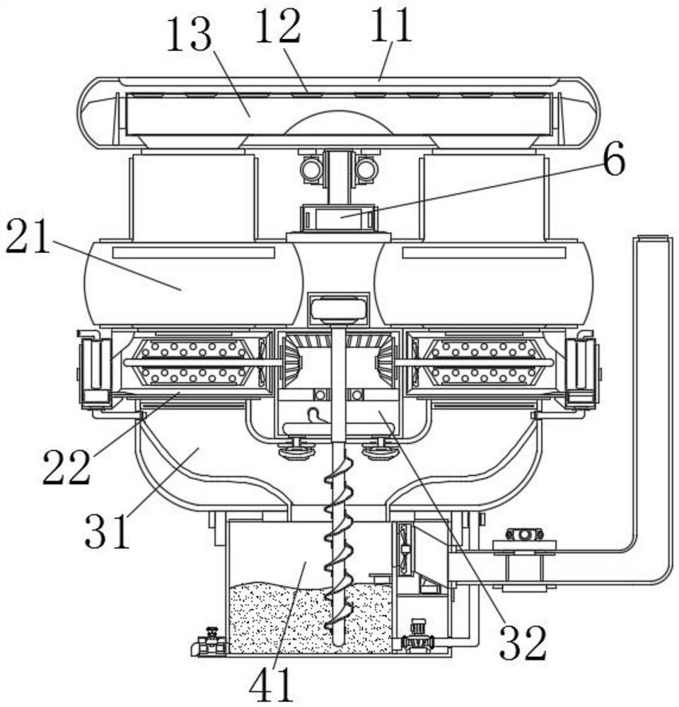
[0043] Example 1, as Figure 1-4 As shown, when the two sets of suction fans 21 are activated, the heat source gas and dust in the body can be sucked into the air guide groove 22 together, and the gas is divided and guided by the rotation of the fan blades 34 and the stirring blades 33. , and the installation of the filter screen plate prevents the dust from entering the U-shaped air duct 31, and promotes the dust to enter the communication groove 393 under the guidance of the rotation of the stirring blade 33 and the fan blade 34. At this time, the entering dust can be passed through the water curtain 392. Adsorption and gas separation and filtration are performed, and the adsorbed dust can adhere to the surface of the water curtain 392 or fall into the filter tank 391, which is convenient for subsequent processing work.

Embodiment 2

[0044] Example 2, as Image 6 As shown in the figure, during the guidance and separation of dust and gas through the air guide groove 22 and the absorption filter system 39, the water can be injected into the water curtain 392 through the water inlet pipe to promote the surface of the water curtain 392 to seep water. The flowing gas assists in cooling, and at the same time, the dust adhering to the surface of the water curtain 392 is discharged, so that the dust is uniformly dropped into the filter tank 391 for collection, and the operability and convenience of the subsequent cleaning work of the structure are increased.

[0045] Working principle: When the equipment is in use, first install the device inside the electronic engraving machine, and then use the temperature monitor 6 to intelligently monitor the temperature control in the body. When the temperature gradually rises beyond the specified index with the start of the body, The suction fan 21 can be automatically activ...


PUM


Abstract

The invention discloses a gravure electronic engraving machine with a built-in intelligent temperature control device, which includes an air guide and flow diversion mechanism, an air suction guide mechanism, a heat dissipation temperature control system and a water circulation cooling mechanism, and the air guide and flow diversion mechanism respectively includes an air inlet and a through hole and a shunt pipe, the shunt pipe is located at the bottom of the air inlet, the top of the shunt pipe is uniformly provided with through holes, and a temperature monitor is fixedly connected to the middle position of the bottom of the air inlet; The connection and cooperation of the flow diversion mechanism, the suction guide mechanism and the heat dissipation temperature control system form an absorption heat dissipation discharge system placed inside the electronic engraving machine, so that the temperature control equipment can quickly absorb the hot air in the body, and during the absorption period The air flow disperses and cools down, prompting the heat source in the gas to decompose and return to the body again to form a gas flow cycle, which can improve the maintenance and stability of the constant temperature in the body.

Description

technical field [0001] The invention relates to the technical field of engraving machines, in particular to a built-in intelligent temperature control device of a gravure electronic engraving machine. Background technique [0002] Electronic engraving gravure is a method that appeared in the 1960s. It uses photographic negatives as originals, and uses an engraving machine with electronic circuits to directly engrave dots on the surface of the copper plate cylinder to make gravure. Its characteristics are: no carbon paper. There is no need to carry out chemical corrosion process, which reduces the quality instability factors and the general problem of public nuisance. Because it is electronic engraving, the level reproduction is stable, and at the same time, any level can be made; making a negative image of an original film, it can engrave many A gravure plate with the same pattern can be used to shorten the photographing process. [0003] During the engraving process of the...

Claims


Application Information

Patent Timeline
Patent Type & Authority Patents(China)
IPC IPC(8): B44B1/06B44B3/06
CPCB44B1/06B44B3/06
Inventor 何辉俊尹立方继康
Owner 深圳市国匠数控科技有限公司
Why Eureka
Try Eureka