
Laser with gain medium configured to provide an integrated optical pump cavity

a gain medium and optical pump technology, applied in the direction of laser details, active medium shape and construction, optical resonator shape and construction, etc., can solve the problems of difficult laser operation, inability to achieve efficient optical pumping of side-pumped laser medium, and inability to achieve high-power laser operation, etc., to achieve efficient extraction of energy from optical pump radiation, low loss, and high conversion efficiency

Inactive Publication Date: 2002-05-16
RAYTHEON CO
View PDF0 Cites 20 Cited by
  • Summary
  • Abstract
  • Description
  • Claims
  • Application Information

AI Technical Summary

Benefits of technology

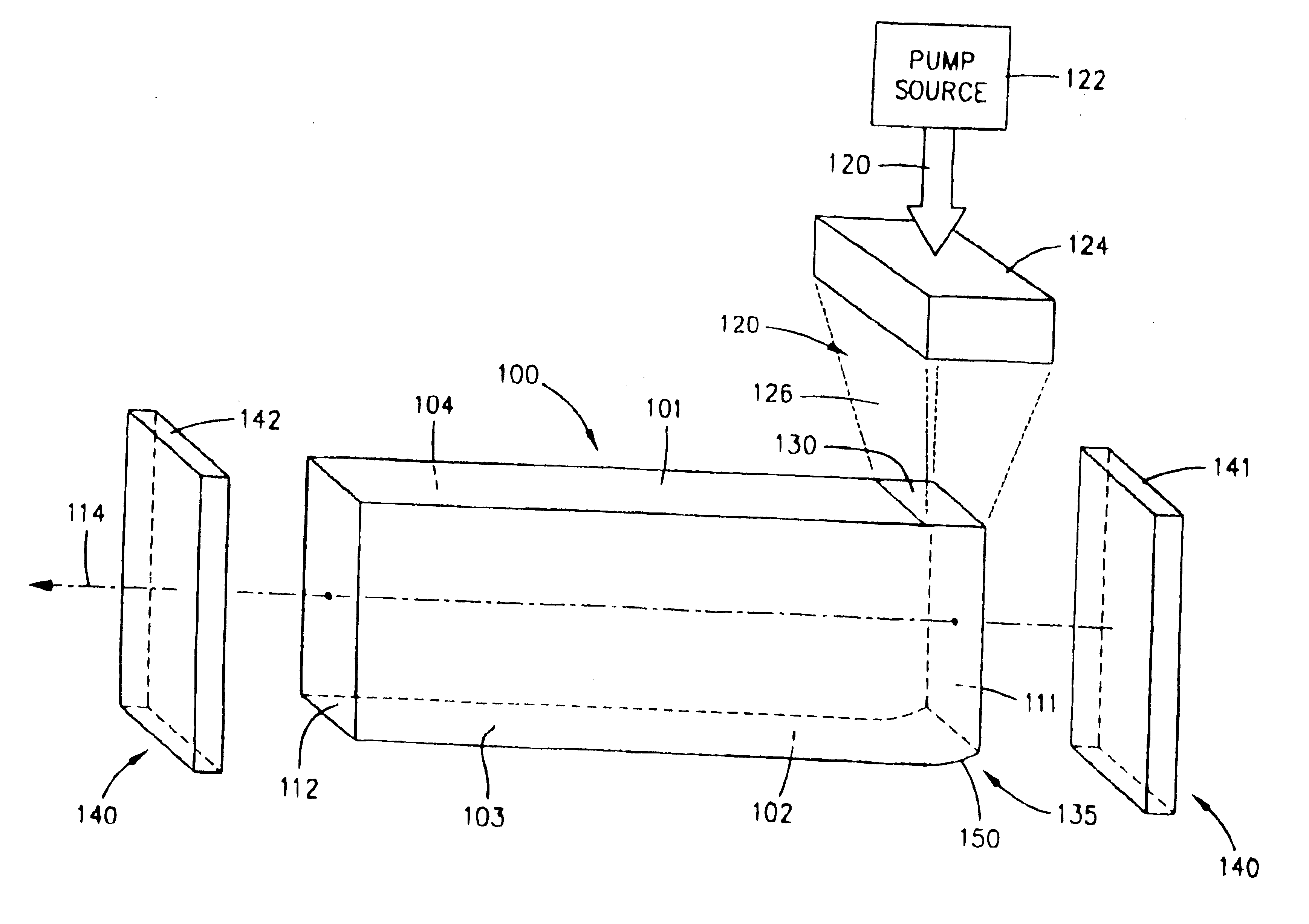
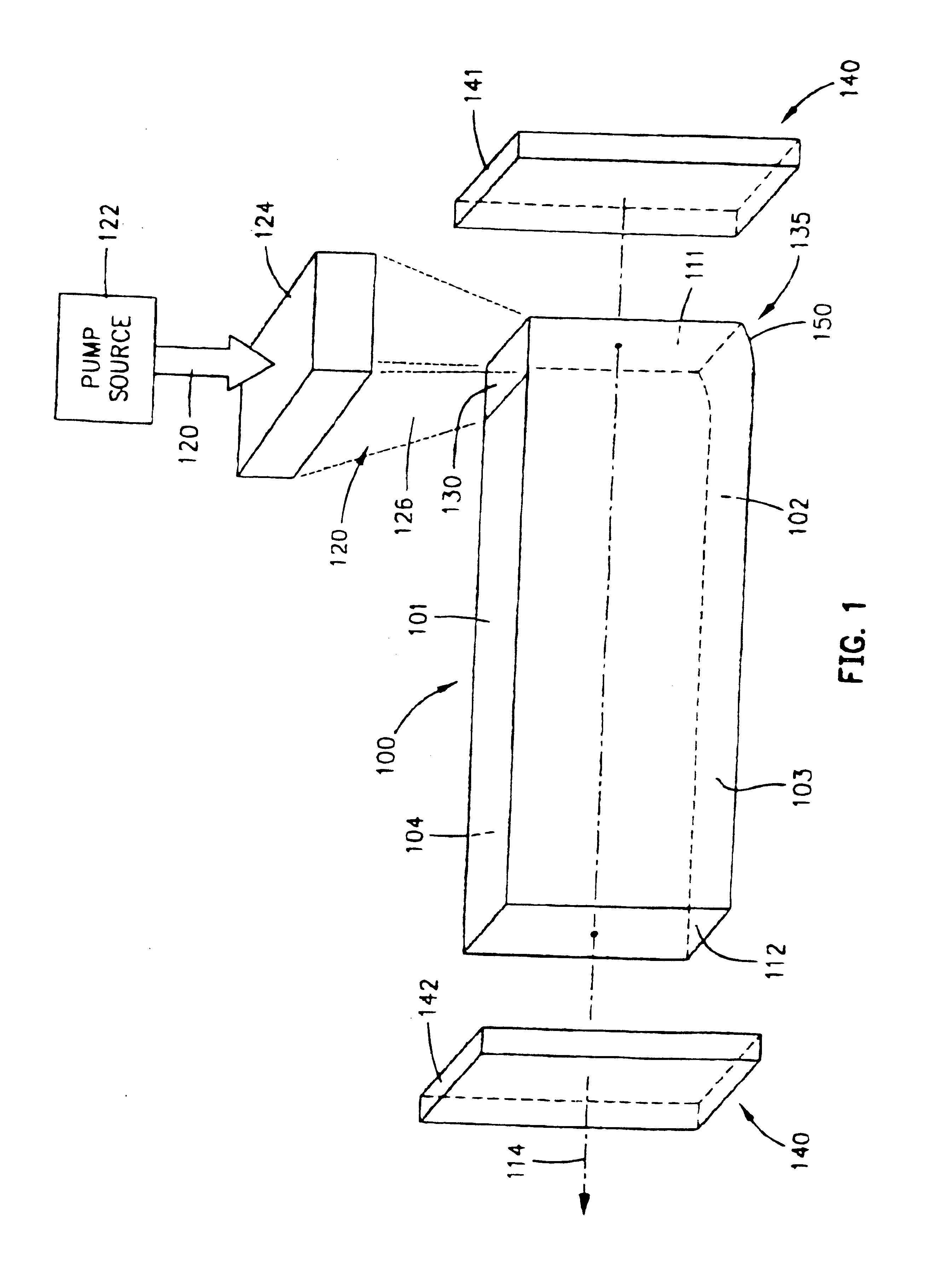
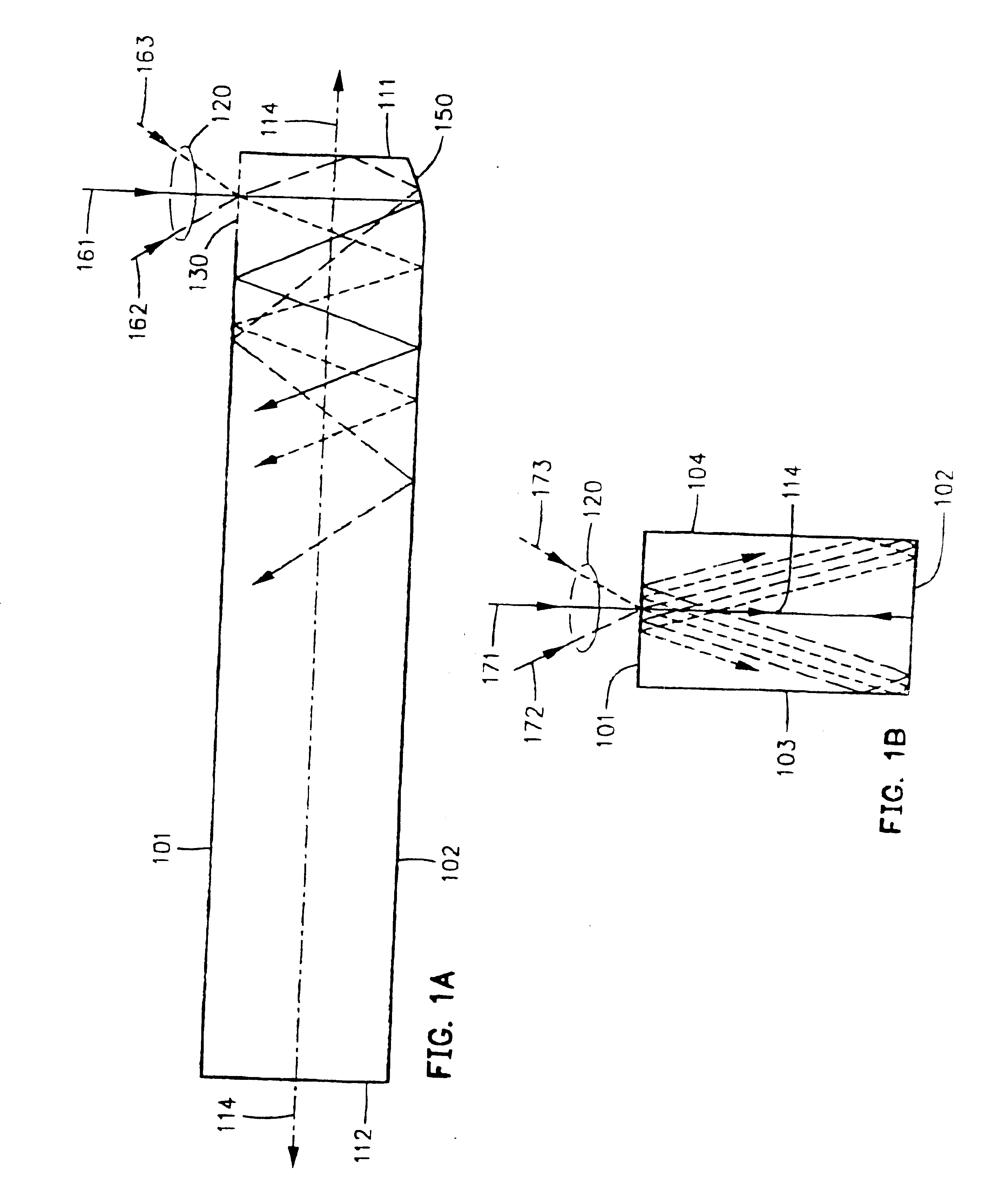
[0012] In order to overcome the limitations of the prior art, the present invention provides an optically-pumped laser having a gain medium configured to provide a low loss, three-dimensional integrated optical pump cavity for injected optical pump radiation. The optical pump cavity re-directs the optical pump radiation throughout the lasing volume in multiple passes, substantially retaining the optical pump radiation within the lasing volume to create an average pump absorption length that can be configured to be much longer than twice the laser axis length, thereby efficiently extracting energy from the optical pump radiation even when very low pump absorptive ion dopant concentration laser media are employed. The integrated pump cavity can be implemented in lasers having a wide range of power levels, from low power lasers to high power lasers that generate one kW or more. Laser embodiments implementing the present invention have been demonstrated to have a high efficiency in converting the input pump energy into laser emission while maintaining uniform pumping distribution. Particularly, some laser embodiments have a concentration Figure of Merit (F.sub.c) greater than 1.0, and in some embodiments exceeding 2.0.
[0015] In some embodiments, the gain medium comprises a solid state gain medium that defines a pump cavity including coated boundaries, thereby integrating the pump cavity with the gain medium. The integrated pump cavity is particularly useful for high power solid state lasers. By carefully designing the pump cavity configuration and appropriately choosing the dopant concentration of the active pump ion within the solid state material, high power optical pump radiation can be absorbed approximately evenly throughout the volume, producing heat more uniformly throughout the solid state laser gain medium, which can reduce or substantially eliminate higher order thermal distortion effects that adversely affect other high power optically-pumped lasers. Also, uniform absorption reduces or substantially eliminates potentially destructive hot areas within the gain medium. One embodiment includes a lightly doped (e.g. <1%) solid state laser gain medium such as Yb:YAG, and the integrated pump cavity includes design features to concentrate the intensity of the optical pump radiation. When pumped to optical transparency conditions, the lightly-doped, quasi-three level solid state laser gain medium produces less heat and lower spontaneous emission losses per unit volume than the other, more highly doped crystals that are used in conventional laser designs.
[0016] Advantageously, a heat sink can be directly coupled to the transverse surfaces of the solid state gain medium, effectively cooling the gain medium and optical coating formed thereon, even for high power operation. Furthermore, detrimental higher order optical distortion effects are reduced because the product of the transverse temperature gradient and the laser axis medium length is minimized through the use of the integrated pump cavity. Also, because the optical pump radiation propagates substantially orthogonal to the laser axis, coating requirements for the end surfaces are simplified and the total intensity proximate to the laser end surfaces is significantly reduced, thereby reducing cost, increasing performance, and improving manufacturing yield.

Problems solved by technology

However, side-pumped laser configurations have many problems, such as conflicting requirements for cooling the laser medium through the medium side surfaces, suppressing parasitic pump cavity oscillations, and controlling the spatial distribution of the optical pump power within the gain medium, while still maintaining a high pump energy absorption efficiency.
These problems are particularly difficult when the side-pumped laser medium has a low absorption of pump energy per transverse pass.
In order to obtain high pumping efficiency in such low absorption media, the pump energy must be retained by the pump cavity and redirected back through the laser medium many times. When the pump energy losses resulting from the successive interactions with the cooling interface, parasitic suppression, and pump cavity optical systems become excessive, efficient optical pumping of the side-pumped laser medium cannot be achieved and high power laser operation may become impossible.
However, significant problems render high power operation difficult to achieve in end-pumped configurations.
For example, excessive optical power intensities are created due to the fact that end-pumped lasers have a common propagation axis for both the pump and extracted laser beams, combined with the fact that a typical laser diode pump beam has a highly non-uniform transverse intensity distribution.
Attempts to design an efficient, practical high power end-pumped laser have encountered problems such as excessive optical power intensity due to the combination of the intensities of the pump and extracted laser beams, severe thermally-induced medium distortion, excessive doping concentration or medium length constraints on design optimization, increased laser resonator optical losses resulting from complex multi-wavelength optical coatings, and spatially non-uniform pumping distributions.
These problems are particularly severe for embodiments in which the laser medium exhibits a high pump saturation flux, such as may result from a low pump absorption cross-section.
In addition to these problems, which can limit the performance and increase the complexity of end-pumped laser embodiments, an additional problem arises for an important class of laser media.
However, such end-pumped configurations have encountered the above-discussed problems, which have restricted scaling them to high average power levels.
Such optimum end-pumped configurations can be impractical to implement, and generally must be compromised to a lower F.sub.c value.
Furthermore, side-pumped pumped embodiments that use external re-entrant pump cavities have a low pump energy absorption efficiency and / or an F.sub.c value significantly lower than 1.0.

Method used


Image

  • Laser with gain medium configured to provide an integrated optical pump cavity
  • Laser with gain medium configured to provide an integrated optical pump cavity
  • Laser with gain medium configured to provide an integrated optical pump cavity

Examples


Embodiment Construction

[0040] This invention is described in the following description with reference to the Figures, in which like numbers represent the same or similar elements.

[0041] As used herein, the angle of incidence of a light ray with a surface is defined with respect to the normal (i.e. perpendicular) to the surface. Light rays incident upon a reflective surface are reflected at an angle that is a function of the angle of incidence. Some surfaces are designed with materials or optical coatings over a range of angles of incidence. However, even if the surface is not designed to be reflective, under certain circumstances an interface between two materials will be reflective to light rays having large angles of incidence, an effect caused by total internal reflection ("TIR"). Specifically, TIR causes a light ray propagating through a material having a high index of refraction to be reflected from an interface with another medium that has a lower index of refraction, if the angle of incidence is la...


PUM


Abstract

An optically-pumped laser having a gain medium configured to provide a low loss, three-dimensional integrated optical pump cavity that substantially confines optical pump radiation within the lasing volume, which is particularly useful for efficiently pumping solid state gain media that has low pump dopant concentration. The integrated pump cavity includes a plurality of boundaries contiguous with the gain medium. An optical pump source such as a laser diode array supplies optical pump radiation that is input into the gain medium through one or more pump cavity windows with a propagation direction transverse to a laser axis defined through the gain medium. In some embodiments, an optical surface is situated opposite the window to approximately recollimate the input pump radiation. The optical pump cavity may be designed to concentrate the optical pump radiation and approximately uniformly pump the entire volume of the lasing medium. In one such embodiment, the pump cavity includes opposing converging surfaces that concentrate the optical pump radiation as it projects along the laser axis. Embodiments are disclosed in which a solid state gain medium has coatings that operate to suppress amplified spontaneous emission ("ASE"). Some embodiments also include heat sinks that directly contact the transverse boundaries and control the temperature distribution within the gain medium in a predetermined manner.

Description

BACKGROUND OF THE INVENTION[0001] 1. Field of the Invention[0002] The present invention generally relates to optically-pumped lasers, and more particularly, to optically-pumped lasers that have a low pump energy absorption per unit length such as may result from a low pump absorption cross-section and / or a low doping concentration of pump absorptive ions.[0003] 2. Description of Related Art[0004] An optically-pumped laser includes a gain medium and an optical pump source that supplies optical pump radiation to the gain medium, where it is converted into a laser emission. Many early optically-pumped lasers utilized high intensity arc lamps that were formed into any suitable shape, such as a linear shape or a helically wrapped configuration. Although these sources emit high intensity light, they are "low radiance" (i.e. they emit over a very large solid angle), and therefore efficiency was greatly improved by using pump cavities to collect and redirect the pump light to illuminate the...

Claims


Application Information

Patent Timeline
Patent Type & Authority Applications(United States)
IPC IPC(8): H01S3/06H01S3/094H01S3/0941
CPCH01S3/06H01S3/0606H01S3/0941H01S3/0612H01S3/094084H01S3/061
Inventor PERESSINI, EUGENE R.
Owner RAYTHEON CO
Learn More