Supercharge Your Innovation With Domain-Expert AI Agents!

Concrete pole hoisting device

A lifting device, cement pole technology, applied in safety devices, transportation and packaging, load hanging components, etc., can solve the problems of low pole efficiency, low compaction efficiency, time-consuming and labor-intensive, etc. Compaction efficiency and anti-shake effect

Pending Publication Date: 2022-01-04
STATE GRID SHANDONG ELECTRIC POWER CO WUCHENG POWER SUPPLY CO +1
View PDF6 Cites 0 Cited by
  • Summary
  • Abstract
  • Description
  • Claims
  • Application Information

AI Technical Summary

Problems solved by technology

[0003] At present, for the second step, a crane is usually used to hang the middle and upper ends of the cement pole through the sling, and then the cement pole is hoisted into the foundation pit. Since the cement pole is in a suspended state, the shaking range is relatively large, resulting in the efficiency of the pole. It is relatively low; moreover, after the pole is erected, the next step of foundation pit filling and tamping operation is required, which requires the use of additional tamping equipment, which not only increases the construction cost, but also the existing tamping equipment needs to move back and forth around the cement pole It is time-consuming and labor-intensive to tamp, and the tamping efficiency is low

Method used


Image

  • Concrete pole hoisting device
  • Concrete pole hoisting device
  • Concrete pole hoisting device

Examples


Embodiment Construction

[0021] Embodiments of the present invention are further described below in conjunction with accompanying drawings:

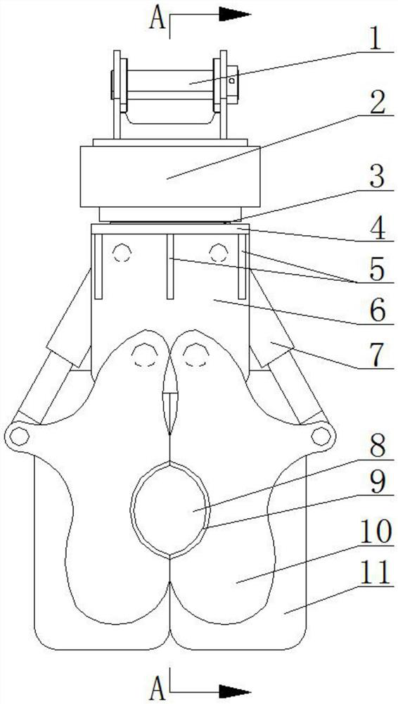
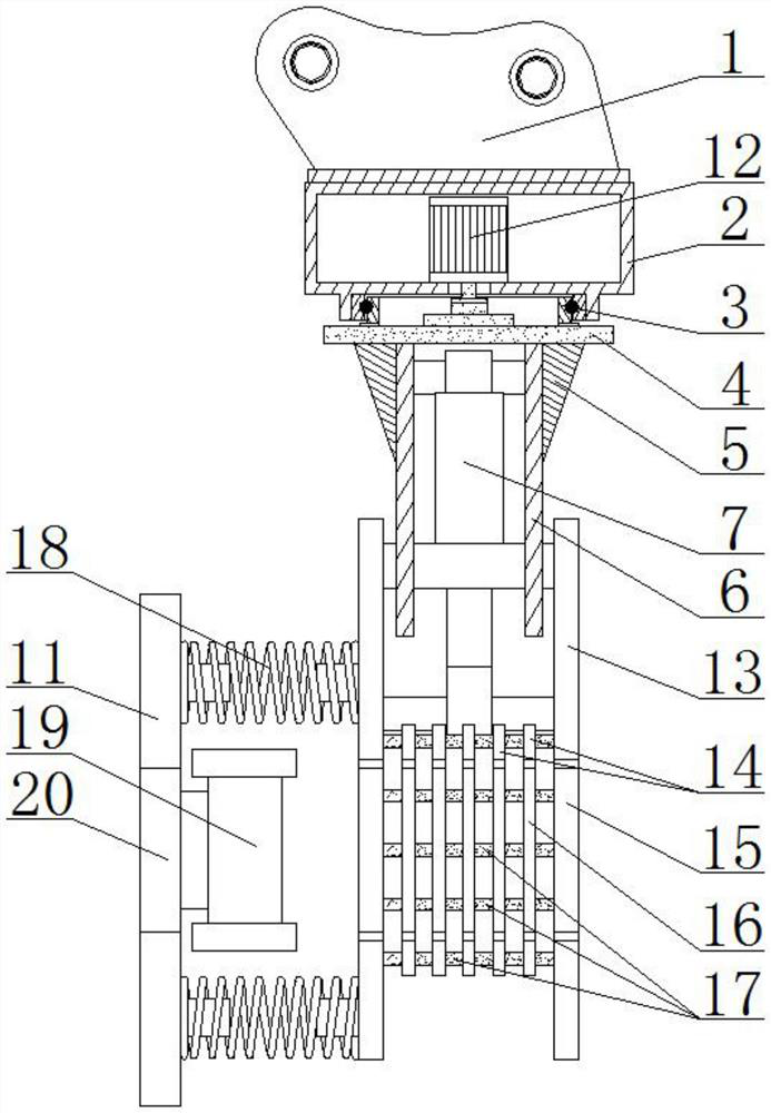
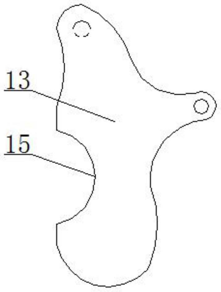
[0022] Such as Figure 1 to Figure 5 As shown, the cement pole lifting device of the present invention includes a connector 1, the bottom of the connector 1 is fixed with a mounting seat 2, and the bottom of the mounting seat 2 is connected to a mounting plate 4 through a rotating structure 3, and the mounting plate 4 is connected There is a rotating drive structure 12, the bottom of the mounting plate 4 is fixed with a mounting frame 6, and the lower end of the mounting frame 6 is hinged with two corresponding clamping claws 10, and the mounting frame 6 is also hinged with two telescopic claws 10 respectively. Structure 7, the two clamping claws 10 are correspondingly provided with a clamping port 8, the rear sides of the two clamping claws 10 are fixed with a tamping plate 11 through a set of vibrating springs 18, and the front sides of the two tamping plates ...


PUM


Abstract

The invention belongs to the field of equipment for erecting concrete poles, and particularly relates to a concrete pole hoisting device. The device comprises a connector, a mounting seat is fixed to the bottom of the connector, a mounting plate is rotationally connected to the bottom of the mounting seat through a rotating structure, the mounting plate is connected with a rotating driving structure, and a mounting frame is fixed to the bottom of the mounting plate. Two corresponding clamping jaws are hinged to the lower end of the mounting frame, two telescopic structures are further hinged between the mounting frame and the two clamping jaws, clamping openings are correspondingly formed in the two clamping jaws, tamping plates are fixed to the rear sides of the two clamping jaws through a set of vibration springs, and vibration motors are fixed to the front sides of the two tamping plates; and notches corresponding to the clamping openings are formed in the two tamping plates. A concrete pole is grabbed and erected through the clamping claws, the concrete pole can be prevented from shaking, and the pole erecting efficiency is improved; and moreover, the tamping plates are driven by the vibration motors to tamp foundation pit soil, additional tamping equipment is not needed, the cost is saved, and the tamping efficiency is improved.

Description

technical field [0001] The invention relates to a lifting device for cement electric poles, which belongs to the field of equipment for vertical poles of cement electric poles. Background technique [0002] Often need to erect new cement electric pole in electric power construction, its step is: the first, dig out a foundation pit earlier; Second, cement electric pole is erected in the foundation pit; Among them, the compaction process needs to continuously repeat the filling-tamping operation to ensure the stability of the cement pole. [0003] At present, for the second step, a crane is usually used to hang the middle and upper ends of the cement pole through the sling, and then the cement pole is hoisted into the foundation pit. Since the cement pole is in a suspended state, the shaking range is relatively large, resulting in the efficiency of the pole. It is relatively low; moreover, after the pole is erected, the next step of foundation pit filling and tamping operatio...

Claims


Application Information

Patent Timeline
Patent Type & Authority Applications(China)
IPC IPC(8): B66C13/06B66C1/44B66C15/04E04H12/34E04H12/12E02D17/02E02D3/046
CPCB66C13/06B66C1/44B66C15/04E04H12/34E04H12/12E02D17/02E02D3/046
Inventor 王保志王梦华孙淑燕王东宝刘楠李丹丹王超黄砚征谢辉于瑞
Owner STATE GRID SHANDONG ELECTRIC POWER CO WUCHENG POWER SUPPLY CO
Features
  • R&D
  • Intellectual Property
  • Life Sciences
  • Materials
  • Tech Scout
  • Unparalleled Data Quality
  • Higher Quality Content
  • 60% Fewer Hallucinations
Learn More