
Magneto-rheological clutch with driving disc of groove structure

A transmission disk and magneto-rheological technology, applied in the direction of fluid clutches, clutches, couplings, etc., can solve the problems of increased energy consumption and temperature rise, and achieve the effects of increasing torque transmission, reducing the maximum temperature rise, and enhancing heat dissipation

Pending Publication Date: 2022-01-04
JIANGSU UNIV
View PDF0 Cites 0 Cited by
  • Summary
  • Abstract
  • Description
  • Claims
  • Application Information

AI Technical Summary

Problems solved by technology

However, the increase of toroidal coils also brings new problems, such as increased energy consumption, temperature rise of the main and driven discs of the clutch and magnetorheological fluid, etc.

Method used


Image

  • Magneto-rheological clutch with driving disc of groove structure
  • Magneto-rheological clutch with driving disc of groove structure
  • Magneto-rheological clutch with driving disc of groove structure

Examples


no. 1 example

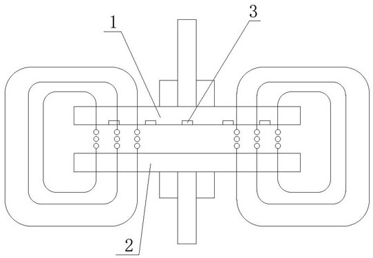
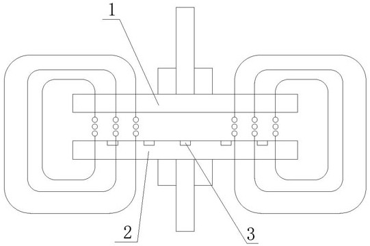
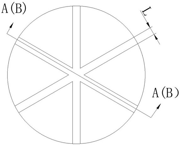
[0039] like image 3 and 4 As shown, the groove 3 is an elongated radial groove extending from the center of the main transmission disc 1 or from the center of the transmission disc 2 along its radial direction, and the number of the elongated radial grooves is at least three , the optimal number of strips is 4-12; the radial grooves are uniformly distributed on the inner surface of the main transmission disc 1 or the secondary transmission disc 2 along the circumferential direction at equal angles. The radial grooves are elongated grooves with equal width, and the width of the radial grooves is 4-10mm. The depths of the radial grooves are equal, and the depth of the radial grooves is 1-5 mm.

[0040] Trench Structure Second Embodiment

[0041] like image 3 and 5 As shown, the groove 3 is an elongated radial groove extending from the center of the main transmission disc 1 or from the center of the transmission disc 2 along its radial direction, and the number of the elon...

no. 5 example

[0047] like Figure 7 and 9 As shown, the grooves 3 are concentric annular grooves distributed at equal intervals along the radial direction from the center of the main transmission disc 1 or the transmission disc 2, and the center-to-center distance of adjacent annular grooves ranges from 10 to 40 mm. The widths of the annular grooves are equal, and the width of the annular grooves is 4-10mm. The depth of the annular groove is reduced one by one by the depth of the outer annular groove of the inner ring, the range of the depth of the annular groove is 1-5mm, and the variation of the depth of the annular groove is the maximum difference of the depth of the annular groove The value is divided by the number of ring slots.

[0048] The sixth embodiment of trench structure

[0049] like Figure 10 and 11 As shown, the grooves 3 are concentric annular grooves distributed at equal intervals along the radial direction from the center of the main transmission disc 1 or the transm...


PUM


Abstract

The invention discloses a magneto-rheological clutch with a driving disc of a groove structure. The magneto-rheological clutch comprises a main driving disc and an auxiliary driving disc, and a liquid medium containing ferromagnetic suspension particles is arranged between the main driving disc and the auxiliary driving disc; and the opposite faces of the main driving disc and the auxiliary driving disc are inner surfaces, a groove is machined in the inner surface of one of the main driving disc and the auxiliary driving disc, and no groove exists in the inner surface of the other opposite driving disc. The magneto-rheological clutch has the beneficial effects that the grooves are formed in the driving disc, so that the shear stress of the magneto-rheological clutch can be effectively enhanced, meanwhile, the surface heat dissipation area of the driving disc is increased, and therefore the comprehensive optimization effects of enhancing the shear moment, enhancing the heat dissipation capacity and reducing the highest temperature rise are achieved.

Description

technical field [0001] The invention relates to a clutch, in particular to a magneto-rheological clutch with a transmission disc in a groove structure, which belongs to the technical field of mechanical transmission. Background technique [0002] In recent years, with the development of "smart materials", under the action of an external magnetic field, the physical properties of magnetorheological fluids, such as thermal conductivity, mechanical properties, especially the rapid reversible changes in rheological properties under the action of a magnetic field, make it in mechanical It is widely used in transmission, aerospace, construction, medical and other fields. It is a liquid composed of ferromagnetic particles with high magnetic permeability, carrier liquid and additives mixed in a certain proportion. When there is no external magnetic field, it has good fluidity. When there is a magnetic field outside, the magnetorheological The ferromagnetic particles in the liquid w...

Claims


Application Information

Patent Timeline
Patent Type & Authority Applications(China)
IPC IPC(8): F16D37/02
CPCF16D37/02F16D2037/002F16D2300/021F16D2300/10
Inventor 贾和坤胡南镕尹必峰徐波匡欣于瀛霄
Owner JIANGSU UNIV
Learn More