Spiral groove machining device and sprial groove machining method for tube

A processing device and processing method technology, applied in the field of pipe spiral groove processing devices, can solve the problems of pipe 2 scars, uneven spiral groove spacing, buckling, etc.

Active Publication Date: 2011-07-20
NITTOKU ENG CO LTD
View PDF5 Cites 5 Cited by
  • Summary
  • Abstract
  • Description
  • Claims
  • Application Information

AI Technical Summary

Problems solved by technology

[0007] However, when the above-mentioned spiral groove is formed, since the round bar core material 1 inserted into the pipe material 2 is pressed against the holder 3 by the center press head 5, when the circular groove is reduced in order to form the spiral groove on a thinner pipe material, When the outer diameter of the rod core material 1 is smaller, there is the following problem: at the winding mouth of the wire rod 6, the tension of the wire rod 6 acts on the stage in the direction perpendicular to the rotation axis of the pipe material 2, and the round rod core material 1 is in the tension direction. Larger bending occurs, so the round bar core 1 embedded in the tube 2 and compressed axially by the center punch 5 will buckle
Therefore, when the wire 6 having such a bend mark is rewound on the pipe 2, the following problems will occur: the winding angle of the wire 6 changes, the pitch of the formed spiral groove is uneven, and the depth of the groove is between 1 and 2. different places will be different
[0009] In addition, in the above-mentioned spiral groove machining process, the pipe material 2 itself into which the round bar core material 1 is inserted is directly held by the clamper 3, so there is a problem that scratches are generated on the portion of the pipe material 2 held by the clamper 3.

Method used


Image

  • Spiral groove machining device and sprial groove machining method for tube
  • Spiral groove machining device and sprial groove machining method for tube
  • Spiral groove machining device and sprial groove machining method for tube

Examples


Embodiment Construction

[0025] Hereinafter, the best mode for carrying out the present invention will be described with reference to the drawings.

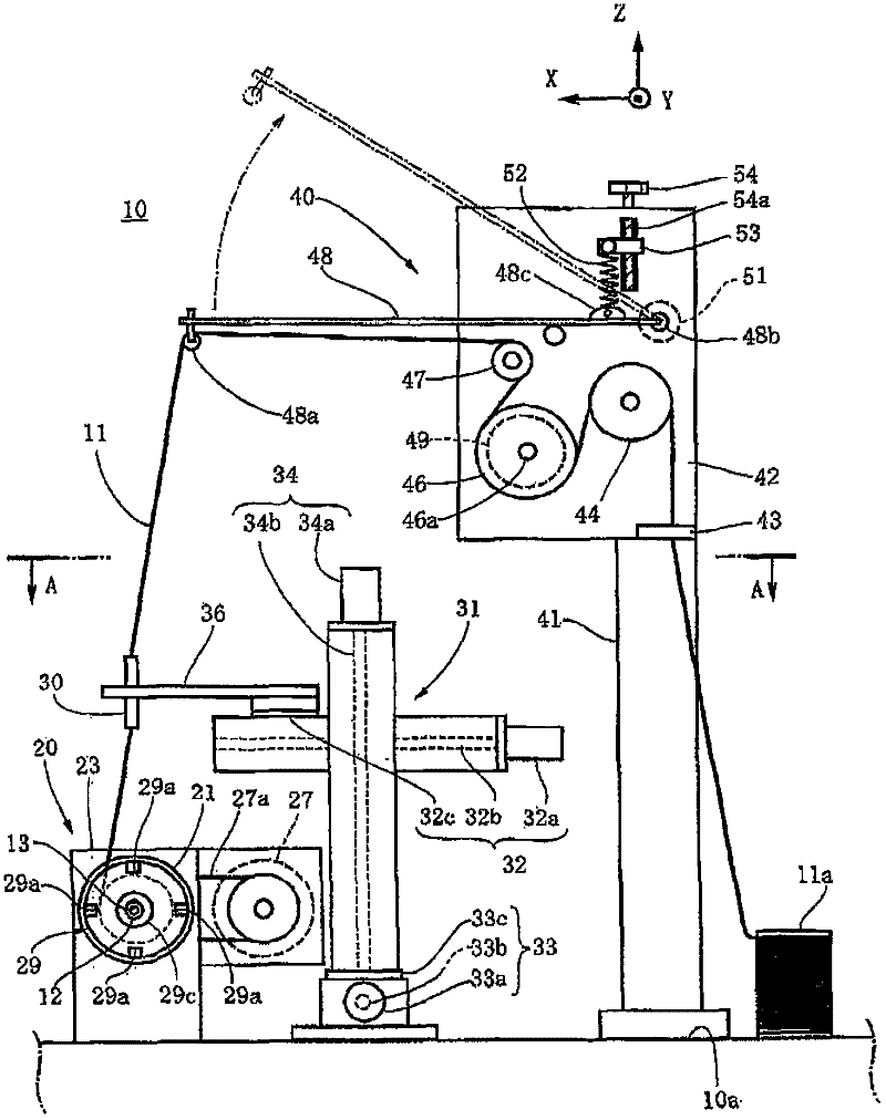
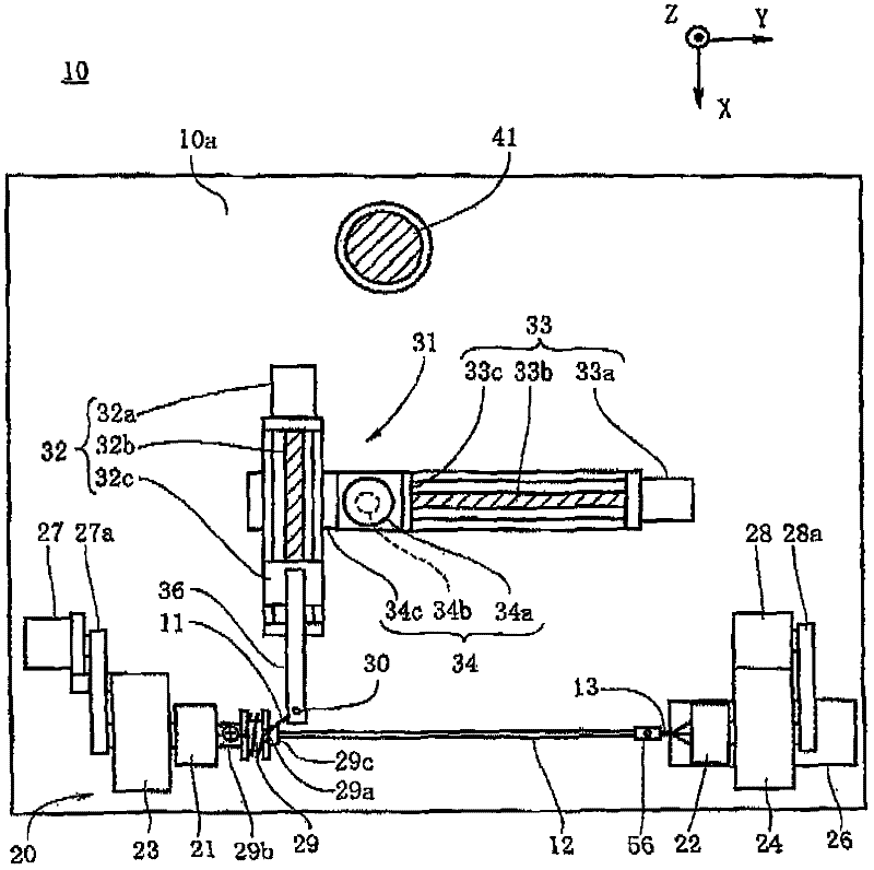
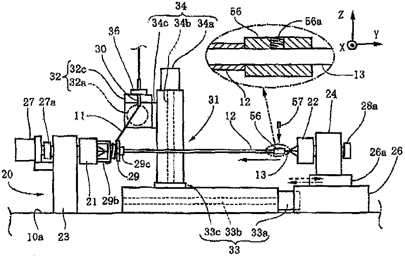
[0026] Such as Figure 1 to Figure 3 As shown, the pipe spiral groove processing device 10 of the present invention is a device that winds the wire 11 derived from the wire supply and discharge mechanism onto the pipe 12, and forms a spiral groove on the outer periphery of the pipe 12, and has a device that can be embedded in the pipe 12. The core wire steel wire 13. As the core wire 13 , for example, hard steel wires such as piano wires can be exemplified. To be able to fit into the pipe material 12 , a steel wire whose outer diameter is the same as or slightly smaller than the inner diameter of the pipe material 12 is selected. In addition, the core wire 13 may have an outer diameter slightly larger than the inner diameter of the pipe material 12 as long as it can be inserted into the pipe material 12 . For example, if the inner diameter of the pipe ...


PUM


Abstract

The present invention provides a spiral groove machining device and a spiral groove machining method for tube. No scratch generates on the tube, and the spiral groove with a certain depth and uniform space can be formed on the tube with a smaller dimension. The spiral groove machining device for tube is provided with the following components: a core steel wire which can be inserted into the tube, a steel wire tensioning mechanism which can tension the core steel wire, and a core wire rotating unit which causes the tensioned core steel wire to rotate clockwise and counterclockwise together with the tube. Preferably the spiral groove machining device for tube is provided with a reel which rotates by means of the core wire rotating unit and can supply the tube that is guided out from a tube supply and discharge mechanism for winding. The spiral groove machining method for tube comprises the following steps: a steel wire tensioning step of tensioning the core steel wire that is inserted into the tube; a tube winding step of clockwise rotating the tensioned core steel wire together with the tube for winding the wire on the tube; a wire drawing-back step of counterclockwise rotating the core steel wire together with the tube for drawing back the wire that is wound on the tube; and a tube detaching step of detaching the tube from the core steel wire.

Description

technical field [0001] The present invention relates to a pipe spiral groove processing device and a pipe spiral groove processing method for winding a wire around a pipe and forming a spiral groove on the outer periphery of the pipe. Background technique [0002] Usually, the endoscope grooved tube through which the treatment tool or the operation wire is inserted is subjected to a bending action according to the bending of the insertion part of the endoscope. The grooved pipe material imparts flexibility that does not interfere with the above-mentioned bending and bending strength that does not cause breakage or buckling. Furthermore, the above-mentioned steel wire is wound along the spiral groove formed on the outer periphery of the grooved pipe material. As a device for forming the spiral groove on such a pipe material, there have been proposed such as Figure 6 The spiral groove processing apparatus shown (for example, refer patent document 1). [0003] Figure 6 The s...

Claims


Application Information

Patent Timeline
Patent Type & Authority Applications(China)
IPC IPC(8): B29C59/02
Inventor 武藤宪一
Owner NITTOKU ENG CO LTD
Why Eureka
Try Eureka