Central range hood, terminal part and air valve control method of range hood

A technology for range hoods and terminal components, which is applied in the field of oil fume removal equipment, and can solve problems such as misjudgment of the switch status of range hoods

Pending Publication Date: 2022-01-04
HANGZHOU ROBAM APPLIANCES CO LTD
View PDF0 Cites 1 Cited by
  • Summary
  • Abstract
  • Description
  • Claims
  • Application Information

AI Technical Summary

Problems solved by technology

[0003] The purpose of the present invention is to provide a central range hood, terminal components and air valve control method of the range ho...

Method used


Image

  • Central range hood, terminal part and air valve control method of range hood
  • Central range hood, terminal part and air valve control method of range hood
  • Central range hood, terminal part and air valve control method of range hood

Examples


Embodiment 1

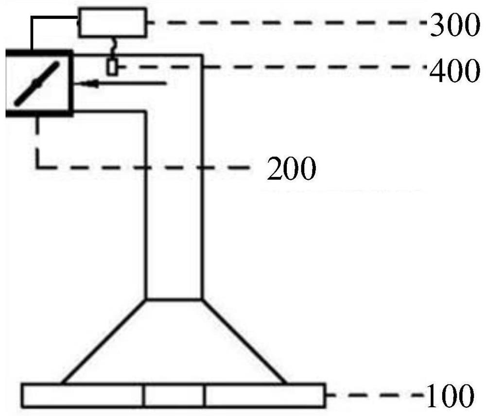
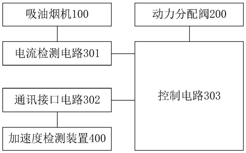
[0029] figure 1 A schematic structural view of a terminal part of a central range hood provided in an embodiment of the present invention, as shown in figure 1 As shown, the terminal components include: a range hood 100 , a power distribution valve 200 , a damper controller 300 and an acceleration detection device 400 .

[0030] The range hood 100 is respectively connected with the power distribution valve 200 and the damper controller 300, and the acceleration detection device 400 is suspended inside the pipeline between the range hood 100 and the power distribution valve 200; the damper controller 300 is respectively connected with the power distribution valve 200 is connected to the acceleration detection device 400.

[0031] The acceleration detection device 400 is used to detect its own suspension acceleration, and send the suspension acceleration to the damper controller 300 .

[0032] The air valve controller 300 is used to detect the working current of the range hood...

Embodiment 2

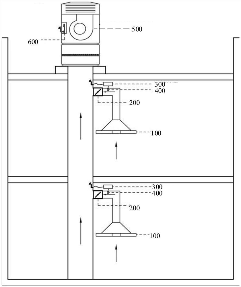
[0059] image 3 A schematic structural diagram of a central range hood provided in an embodiment of the present invention, as shown in image 3 As shown, the central range hood includes: a fan 500, a main controller 600, and terminal components of any one of the central range hoods in the first embodiment above located on each floor.

[0060] The main controller 600 is respectively connected with the fan 500 and the damper controller 300 in each terminal component.

[0061] The damper controller 300 is used to send the working status of the range hood 100 to the main controller 600 .

[0062] The main controller 600 is used for sending the operation frequency information to the fans 500 according to the working states of the range hoods 100 on all floors.

[0063] The fan 500 is used for exhausting air according to the operating frequency information.

[0064] Specifically, the terminal components on each floor in the central range hood are communicatively connected to the ...

Embodiment 3

[0070] Figure 4 A flow chart of a damper control method for a range hood provided in an embodiment of the present invention, the method is applied to the damper controller in any terminal part of the central range hood in the first embodiment above, such as Figure 4 As shown, the method specifically includes the following steps:

[0071] Step S102, detecting the operating current of the range hood, and receiving the suspension acceleration of the acceleration detection device.

[0072] Specifically, when the damper controller controls the opening of the power distribution valve (referred to as the damper), it first needs to determine the working state of the range hood. In the embodiment of the present invention, the damper controller first needs to detect the range hood working current, and at the same time will receive the suspension acceleration sent by the acceleration detection device connected to it in communication.

[0073] Step S104, when the working current is gr...


PUM


Abstract

The invention provides a central range hood, a terminal part and an air valve control method of the range hood, and relates to the technical field of oil smoke removal equipment. The terminal part of the central range hood comprises a range hood, a power distribution valve, an air valve controller and an acceleration detection device; the acceleration detection device detects the self dangling acceleration and sends the self dangling acceleration to the air valve controller; and the air valve controller detects the working current of the range hood and determines the working state of the range hood based on the working current and the dangling acceleration so as to control the opening degree of the power distribution valve. Compared with a terminal part in the prior art, the terminal part has the advantages that the acceleration detection device is additionally arranged in a pipeline, the air valve controller can accurately judge the working state of the range hood by combining the dangling acceleration of the acceleration detection device and the working current of the range hood, then the opening degree of the power distribution valve can be accurately controlled, the technical problem of misjudgment of the on-off state of the range hood is effectively solved, and the kitchen smoke exhaust effect of a user is improved.

Description

technical field [0001] The invention relates to the technical field of oil fume removal equipment, in particular to a central range hood, a terminal component and a method for controlling an air valve of the range hood. Background technique [0002] In the prior art, the central range hood is installed on the terminal parts of each floor, and the switch state of the range hood is identified by detecting the load current of the range hood inside. However, this solution is not suitable for some brands of range hoods. Not applicable, because the value of the lighting current of the range hood is relatively close to the value of the fan current in the low-level operating state, so in practical applications, there may be a problem of misjudgment of the switch status of the range hood, resulting in the air valve controller not being able to accurately control the power The opening of the distribution valve will lead to abnormal adjustment of the air volume by the host, which will ...

Claims


Application Information

Patent Timeline
IPC IPC(8): F24C15/20
CPCF24C15/2021
Inventor 任富佳李海涛陈晓伟
Owner HANGZHOU ROBAM APPLIANCES CO LTD
Why Eureka
Try Eureka