
Low-resistance valve capable of precisely controlling flow rate

A technology for precise control and control of valves, applied in valve details, valve devices, sliding valves, etc., can solve the problems of valve wear, valve disc easily worn, and valve body pressure drop, etc., to reduce fluid loss and eliminate flow. Dead zone, effect of wide fluid passage

Inactive Publication Date: 2013-05-01
BEIJING UNIV OF CHEM TECH
View PDF12 Cites 1 Cited by
  • Summary
  • Abstract
  • Description
  • Claims
  • Application Information

AI Technical Summary

Problems solved by technology

[0004] (1) The flow control is determined by the opening of the valve. The relationship between the opening of the valve and the flow can be quantitatively determined according to the size of the fluid channel in the valve body. The existing valves cannot accurately control the opening of the valve, so as to control size of flow
[0005] (2) The fluid channel of the existing valve is generally horizontal S-shaped. When the fluid enters from the valve inlet, it is easy to accumulate in the valve, which affects the working effect of the valve. At the same time, the pressure drop in the valve body is very large, which is not conducive to the valve work efficiently
[0006] (3) In some large-flux pipelines and equipment, the fluid has a great impact on the valve disc, and the valve disc is easily worn
[0007] (4) In some pipelines and equipment with high sealing and cutting requirements, some solid impurities are inevitably contained in the fluid, and these tiny particles of impurities are sandwiched between the sealing surface of the valve seat and the valve disc, causing the valve to cut continuously. Or leakage is caused by repeated openings that wear the sealing surface, so the sealing between the disc and the valve body is also a big problem
[0008] (5) The roughness in the valve body affects the resistance of the surface of the valve body to the fluid, which increases the pressure drop in the valve body

Method used


Image

  • Low-resistance valve capable of precisely controlling flow rate

Examples


Embodiment Construction

[0025] Below in conjunction with accompanying drawing, the present invention will be further described.

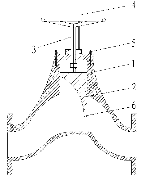
[0026] In the valve body of the present invention, the fluid flows along the C-shaped flow channel, the flow channel is more smooth, and the fluid is distributed in a streamlined manner; the upper part of the valve disc is rectangular, and the lower part is arc-shaped, which can effectively reduce the impact of the fluid on the baffle; the valve disc and the valve body The seal adopts a hemispherical sealing groove; after the valve body is cast, the inner surface of the valve body 1 is finely processed, and the maximum roughness of the processing is 3.2 μm; , first adjust the spiral micrometer structure upwards, when the valve disc is adjusted to the approximate position, adjust the spiral micrometer structure downward, stop rotating after making a sound, and can accurately display and control the valve opening; adjust the valve disc to reduce the flow rate , first adjust ...


PUM


Abstract

The invention discloses a low-resistance valve capable of precisely controlling a flow rate, which belongs to the technical field of fluid conveying. A valve rod 3 is combined with a helical micrometer structure 4, and by utilizing the principle of a helical micrometer instrument, the openness of the valve can be precisely displayed and controlled; fluid of a valve body 1 flows along a C-shaped runner, the fluid is distributed in a linear way, and the runner is smoother; the upper part of a valve clack 2 is in a rectangular shape, and the lower part of the valve clack 2 is in an arc shape; and the valve clack 2 and the valve body 1 are sealed by a semispherical sealing groove 6. The low-resistance valve capable of precisely controlling the flow rate can overcome the defects of the prior art, not only can precisely control the flow rate, but also has the advantages of convenience in opening, precision in controlling, no leakage and small pressure reduction.

Description

technical field [0001] The invention relates to an improved valve, in particular to a valve with low resistance and precise flow control, belonging to the technical field of fluid delivery. [0002] Background technique [0003] Valves are widely used in petroleum, chemical industry, metallurgy, electric power, water treatment and other production fields, mainly to control the on and off of fluid. Every year, valve manufacturers and design and research units are conducting research and design of new valves, but the existing valves are often unsatisfactory in terms of precise flow control, and there are the following deficiencies. [0004] (1) The flow control is determined by the opening of the valve. The relationship between the opening of the valve and the flow can be quantitatively determined according to the size of the fluid channel in the valve body. The existing valves cannot accurately control the opening of the valve, so as to control The size of the flow. [000...

Claims


Application Information

Patent Timeline
IPC IPC(8): F16K3/00F16K27/04F16K37/00
Inventor 李群生
Owner BEIJING UNIV OF CHEM TECH
Learn More