Mechanism for controlling position of variable valve

A valve position, variable technology, applied in the valve device, valve operation/release device, valve details, etc., can solve the problem that the valve opening cannot be intelligently controlled, the range of the opening is arbitrary, etc., to achieve high precision, high opening Accurate range and strong stability

Pending Publication Date: 2019-05-07
天津市北方阀门控制设备有限公司
View PDF6 Cites 1 Cited by
  • Summary
  • Abstract
  • Description
  • Claims
  • Application Information

AI Technical Summary

Problems solved by technology

[0004] Aiming at the deficiencies of the existing technology, the purpose of the present invention is to provide a mechanism for controlling the position of the variable valve, so as to solve the problem that the opening of the valve in the prior art cannot be intelligently controlled, and the size of the water flow can only be used to judge whether the valve is opened or not. Or open small, and the range of opening is relatively random

Method used


Image

  • Mechanism for controlling position of variable valve
  • Mechanism for controlling position of variable valve
  • Mechanism for controlling position of variable valve

Examples


Embodiment Construction

[0014] In order to make the technical means, creative features, goals and effects achieved by the present invention easy to understand, the present invention will be further described below in conjunction with specific embodiments.

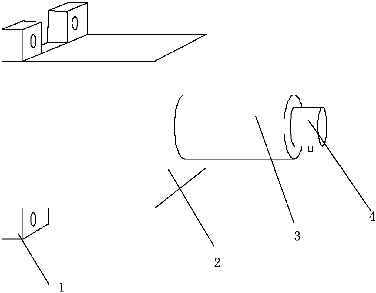
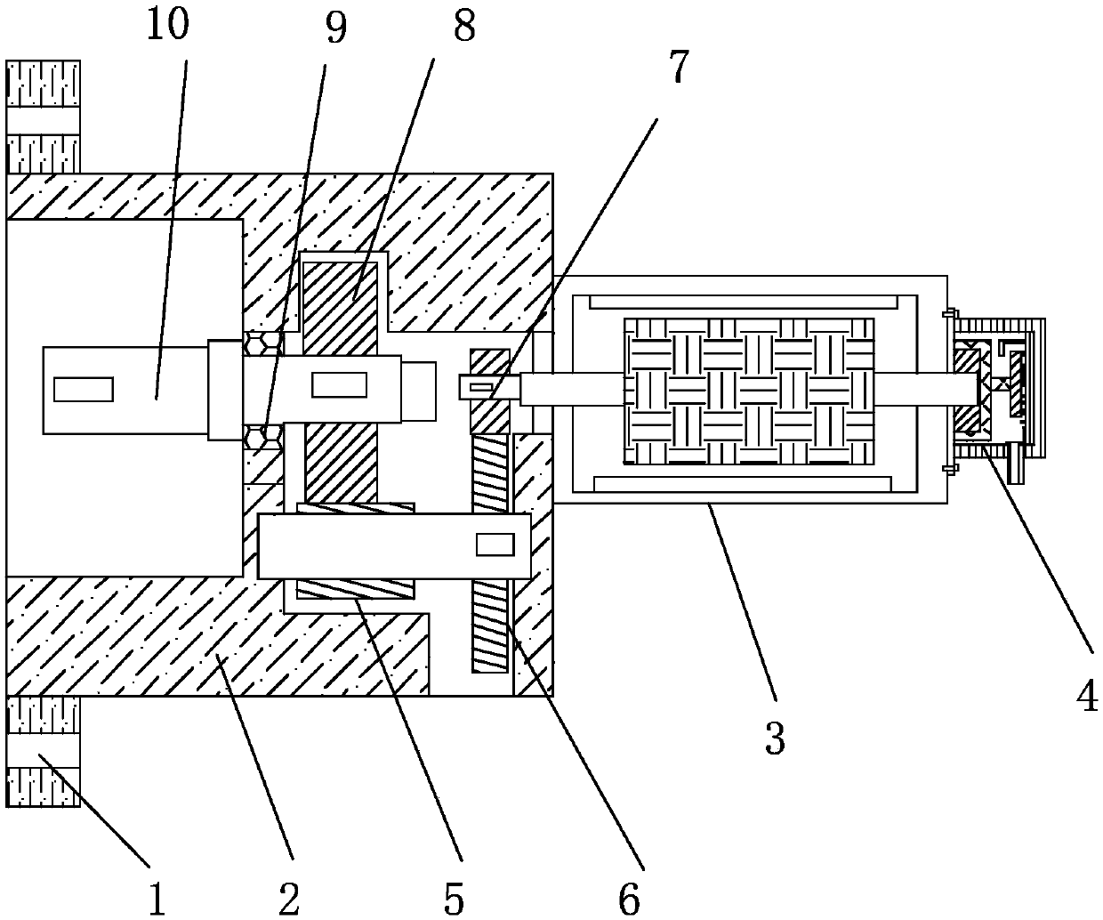
[0015] see Figure 1-Figure 3 , the present invention provides a mechanism for controlling the position of a variable valve: its structure includes: a fixed ear 1, a machine base 2, a servo motor 3, an encoder 4, a secondary gear shaft 5, a primary gear 6, a Stage pinion 7, stage two large gear 8, bearing 9, output shaft 10, the base 2 is fixed on the left side of the servo motor 3 and connected by bolts, the right side of the servo motor 3 is equipped with an encoder 4 and is connected by screws connection, the output shaft 10 is fixed inside the machine base 2 and adopts clearance fit, and the four fixed ears 1 are installed on the upper and lower sides of the machine base 2 and fixed by welding. The first-stage pinion 7 is installed on the serv...


PUM


Abstract

The invention discloses a mechanism for controlling a position of a variable valve. The mechanism comprises fixed lugs, a stand, a servo motor, an encoder, a second-grade gear shaft, a first-grade large gear, a first-grade small gear, a second-grade large gear, a bearing and an output shaft; the stand is fixed on the left side of the servo motor, and is connected by adopting a bolt; the encoder ismounted on the right side of the servo motor, and is connected by adopting a bolt; the output shaft is fixed in the stand, and is in clearance fit; four fixed lugs are provided and mounted on the upper and lower sides of the stand, and are fixed by welding; and the first-grade small gear is mounted on the left side of the servo motor, and is in interference fit. The encoder is provided with a photoelectric receiver, a photoelectric emitter, a shell, a circuit board, a coded disc and a connecting shaft; and through the improved prior art, the openness of the valve is detected by adopting the encoder, so that the openness of the valve can be precisely controlled, the magnitude of water currents is not needed to judge if the valve is opened large or small, and the openness range is more precise.

Description

technical field [0001] The invention relates to a mechanism for controlling the position of a variable valve, which belongs to the field of valve body equipment. Background technique [0002] Control valve, also known as control valve, in the field of industrial automation process control, is the final control element to change the process parameters such as medium flow, pressure, temperature and liquid level by means of power operation by receiving the control signal output by the control unit [0003] The prior art discloses a mechanism for controlling the position of a variable valve, which mainly includes an exhaust device, a sensor, a drive valve and a controller; The exhaust passage of the exhaust gas, the exhaust passage is provided with an exhaust purification device; the sensor is provided with the exhaust device and is located near the exhaust purification device, for detecting the pressure difference of the exhaust gas and for generating a pressure signal; the ac...

Claims


Application Information

Patent Timeline
Patent Type & Authority Applications(China)
IPC IPC(8): F16K31/04F16K37/00
Inventor 黄臶
Owner 天津市北方阀门控制设备有限公司
Why Eureka
Try Eureka