A construction site cable detection equipment

A detection equipment and construction site technology, applied in electromagnetic measuring devices, electric/magnetic solid deformation measurement, electric/magnetic contour/curvature measurement, etc., can solve problems such as low detection efficiency, cable damage and deformation, difficult to observe cables, etc., to achieve Ensure stable transportation and facilitate the effect of deformation

Active Publication Date: 2022-03-08
山东隽宇电子科技有限公司
View PDF20 Cites 0 Cited by
  • Summary
  • Abstract
  • Description
  • Claims
  • Application Information

AI Technical Summary

Problems solved by technology

[0004] The above-mentioned invention still has the following shortcomings: in the cable installation process, it is necessary to check whether the appearance of the power cable is deformed. The inspection method is generally to check the appearance of the power cable manually, which not only increases the number of workers The labor intensity and human work may also lead to missed inspections, resulting in low accuracy. In addition, by setting a metal ring with a slightly larger diameter than the cable, if the cable deformation is too large, the cable pushes the metal ring to touch the switch. , so as to remind the testing personnel, but the non-deformable metal ring is easy to cause secondary damage and deformation of the outer side of the cable, and the outer side of the cable is not easy to observe, resulting in low detection efficiency and inaccurate detection, which further greatly reduces the efficiency of cable detection

Method used


Image

  • A construction site cable detection equipment
  • A construction site cable detection equipment
  • A construction site cable detection equipment

Examples


Embodiment Construction

[0033] The present invention will be described in detail below, and the technical solutions in the embodiments of the present invention will be clearly and completely described. Apparently, the described embodiments are only some of the embodiments of the present invention, not all of them. Based on the embodiments of the present invention, all other embodiments obtained by persons of ordinary skill in the art without making creative efforts belong to the protection scope of the present invention.

[0034] The present invention provides a kind of construction site cable detection equipment here through improvement, and the technical scheme of the present invention is:

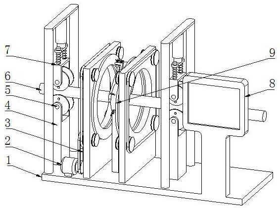
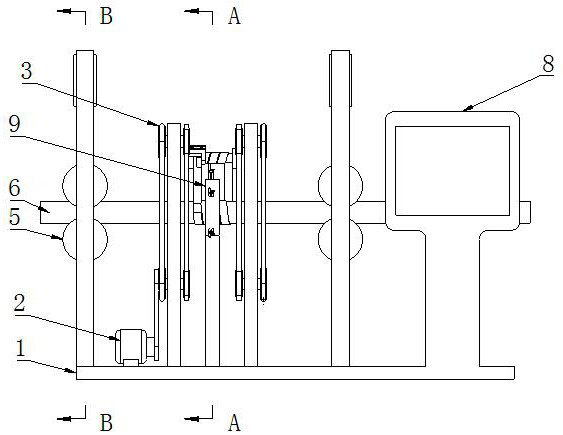
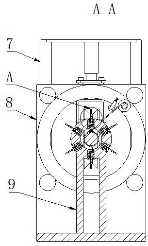
[0035] Such as Figure 1-Figure 14 As shown, a construction site cable detection device includes a bottom plate 1, positioning components are installed on both sides of the top of the bottom plate 1, a cable body 6 is arranged between the two positioning components, and a winding component 3 is installed on the t...


PUM


Abstract

The present invention relates to the technical field of cable detection, in particular to a construction site cable detection device, comprising a bottom plate, positioning components are installed on both sides of the top of the bottom plate, a cable body is arranged between the two positioning components, and the bottom plate The winding assembly is installed on the top, and the winding assembly is located between the two positioning assemblies. The winding assembly includes two mutually parallel support plates, two mutually parallel ring plates and adhesive strips, and the support plate is fixed on On the top of the bottom plate, a penetrating hole is opened in the middle of the outer wall of one side of the support plate, and rotation holes are opened at the four corners of the outer wall of one side of the support plate, and a rotation rod is installed on the inner wall of the rotation hole. The outer wall of the same side of the four rotating rods is fixed with support wheels, and the outer wall of the other side of the four rotating rods is equipped with a transmission assembly. The present invention can visually observe the protrusion and quickly find the position of the protrusion of the cable.

Description

technical field [0001] The invention relates to the technical field of cable detection, in particular to a construction site cable detection device. Background technique [0002] The cable is usually a rope-like cable twisted by several or several groups of wires. Each group of wires is insulated from each other, and is often twisted around a center, and the entire outside is covered with a highly insulating covering. The cable has the characteristics of internal electrification and external insulation. [0003] The publication number is CN112945290A, which discloses a cable detection device in China, which relates to the field of cable detection equipment, including a winding frame, and the winding frame is provided with a winding roller and a detection mechanism. The rewinding frame is rotatably connected, the detection mechanism includes a bracket, a detection sleeve and an alarm unit, the support is fixedly connected with the rewinding frame, and the detection sleeve in...

Claims


Application Information

Patent Timeline
Patent Type & Authority Patents(China)
IPC IPC(8): G01B7/16G01B7/28G01B5/02
CPCG01B7/18G01B7/28G01B5/02
Inventor 于孝传任宏伟何宗涛魏光华程连涛
Owner 山东隽宇电子科技有限公司
Why Eureka
Try Eureka