Method for quickly establishing drainage model through CAD (computer aided design) data and GIS (geographic information system) of data

A data and model technology, applied in the field of data GIS, can solve problems such as abnormal pipeline topology, difficulties in CAD data conversion, and large gaps in geographic information database formats

Pending Publication Date: 2022-01-04
SHANGHAI URBAN CONSTR DESIGN RES INST GRP CO LTD
View PDF0 Cites 0 Cited by
  • Summary
  • Abstract
  • Description
  • Claims
  • Application Information

AI Technical Summary

Problems solved by technology

[0005] 1. Due to the large amount of data in the urban drainage system, if a purely manual method is used to convert CAD data to GIS in order to establish a drainage model, it will greatly increase the workload of the engineer and the construction time of the drainage model
[0006] 2. CAD is the data format of the drawing type, which is quite different from the GIS-like geographic information database format used by the drainage model
Importing CAD data with abnormal topology into the drainage model will also lead to abnormal topology of the pipeline in the model, so engineers need to check the connectivity of the imported topology data one by one
[0007] 3. Since the corresponding attribute information of inspection wells and pipelines in CAD drawings are drawings marks, in the GIS process, engineers need to manually identify the marks and then fill them in the GIS. A large number of manual identification processes are likely to cause data corruption. Wrong filling
[0008] 4. Since different survey and design units use different CAD drawing software when drawing CAD files, and different survey and design units have different drawing habits when drawing, there are problems in the annotation format and pipeline relationship of the CAD data as the original data. Large differences lead to great difficulties in the conversion of CAD data in drainage models and GIS

Method used


Image

  • Method for quickly establishing drainage model through CAD (computer aided design) data and GIS (geographic information system) of data
  • Method for quickly establishing drainage model through CAD (computer aided design) data and GIS (geographic information system) of data

Examples


Embodiment

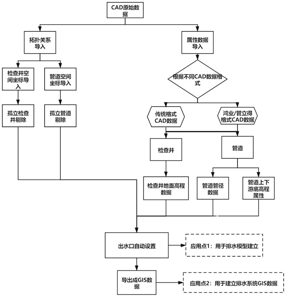
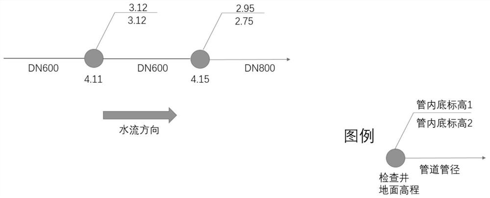
[0043] Such as figure 1 and figure 2 As shown, the method of quickly establishing a drainage model and data GIS through CAD data; using ArcGIS geographic information software and InfoWorks drainage model software to implement, or using QGIS geographic information software and MIKE drainage model software to implement, including the following steps:

[0044] Step 1. Import topological data into the model; import topological data including CAD data and topological relationships into the model; obtain the spatial relationship and connectivity relationship of inspection wells, and the spatial relationship and connectivity relationship of pipelines;

[0045] Step 2, removing isolated pipelines and isolated inspection wells;

[0046] Use the SQL retrieval language to judge each inspection well and each pipeline one by one;

[0047] The method for judging whether each inspection well is isolated is as follows:

[0048] For the ID number of the inspection well that needs to be jud...


PUM


Abstract

The invention discloses a method for quickly establishing a drainage model through CAD (Computer Aided Design) data and GIS (Geographic Information System) of the data. The method the following steps of 1, importing topological data into a model; 2, removing isolated pipelines and isolated inspection wells; 3, importing attribute data of each pipeline and each inspection well; 4, automatically determining a water outlet of the system; and 5, exporting the data of the model as GIS (Geographic Information System) data. According to the method, under the condition that drainage system GIS data is lacked, different scales of drainage model topology construction and pipeline attribute assignment work can be completed in a short time according to CAD pipeline data, and drainage pipe network data in a CAD format can be quickly converted into a universal GIS data format with attributes in a batch mode, and common errors such as isolated nodes and pipelines in the CAD data of the drainage pipeline can be identified in batches and automatically deleted.

Description

technical field [0001] The invention relates to the technical field of computer-aided design, in particular to a method for quickly establishing a drainage model and GIS data through CAD data. Background technique [0002] The traditional hydraulic model based on experience and numerical values ​​has become an important means of drainage system evaluation and design verification in developed countries and regions. China's mega-cities began to explore drainage models in the early 20th century, and up to now, first- and second-tier cities have established drainage models of different scales. In the "Outdoor Drainage Design Standards" GB 50014-2021 revised in 2021, it is clearly required that when the catchment area is greater than 2 square kilometers, a mathematical model should be used to determine the rainwater design flow. With the continuous development of modeling technology and experience, there will be more and more demands for drainage model establishment in the futur...

Claims


Application Information

Patent Timeline
Patent Type & Authority Applications(China)
IPC IPC(8): G06F30/18G06F111/10
CPCG06F30/18G06F2111/10
Inventor 陈泽伟纪莎莎何黎姜莉
Owner SHANGHAI URBAN CONSTR DESIGN RES INST GRP CO LTD
Why Eureka
Try Eureka