
Paralyzed patient lifting device

A lifting device and patient technology, applied in medical science, hospital beds, hospital equipment, etc., can solve problems such as easy falling and patient falling, and achieve the effect of less floor space, avoiding shaking and rotation, and good stability

Active Publication Date: 2022-01-07
THE FIRST AFFILIATED HOSPITAL OF ANHUI MEDICAL UNIV
View PDF11 Cites 0 Cited by
  • Summary
  • Abstract
  • Description
  • Claims
  • Application Information

AI Technical Summary

Problems solved by technology

The most common problem for these paraplegic patients is getting up to the wheelchair, because the patient can move when they get on the wheelchair, but there is a distance between the bed and the wheelchair, and the patient is likely to fall, because there is a distance between the bed and the wheelchair, Especially dragging the cumbersome lower body, it is easy to fall down. Therefore, a device that is convenient for the patient to move between the bed and the wheelchair has just been arranged on the market. For example, the notification number is CN210096176U. A lifting auxiliary device for transferring between wheelchairs, relates to the technical field of medical equipment, and includes a support frame, a chute is provided on the opposite surface of the support frame, and sliding blocks are slidably connected in the two chute slots, and the two The opposite surfaces of the slider are respectively fixedly connected to the ends of the two fixed rods which are far away from each other, and the ends of the two fixed rods which are close to each other are respectively fixedly connected to the left and right sides of the ring

Method used


Image

  • Paralyzed patient lifting device
  • Paralyzed patient lifting device
  • Paralyzed patient lifting device

Examples


Embodiment Construction

[0036] The following will clearly and completely describe the technical solutions in the embodiments of the present invention with reference to the accompanying drawings in the embodiments of the present invention. Obviously, the described embodiments are only some, not all, embodiments of the present invention. Based on the embodiments of the present invention, all other embodiments obtained by persons of ordinary skill in the art without making creative efforts belong to the protection scope of the present invention.

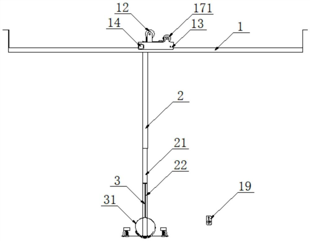
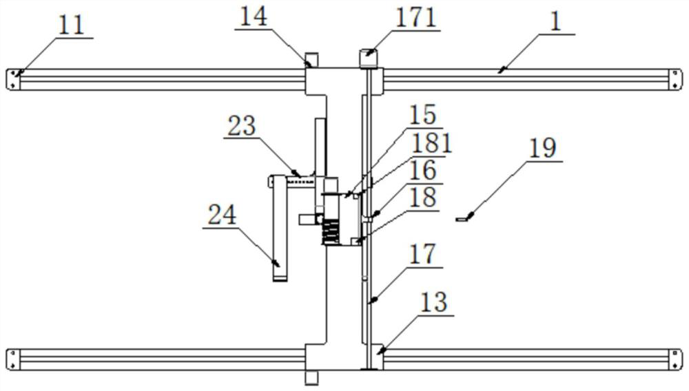
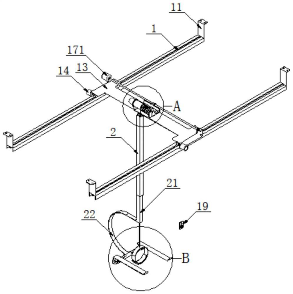
[0037] see Figures 1 to 9 , the left and right ends here correspond to the left and right hands, the rear end refers to the side that the reader looks at, and the side close to the reader is the front side. This is just for the convenience of description, and does not represent the actual position and direction. Device technical solution: a lifting device for paralyzed patients, including a crane mechanism capable of moving back and forth, left and right, a ver...


PUM


Abstract

The invention discloses a paralyzed patient lifting device. The paralyzed patient lifting device comprises a crown block mechanism capable of moving front, back, left and right, a vertical guide mechanism, an arm supporting mechanism and a waist hanging mechanism. The crown block mechanism comprises a front guide rail and a rear guide rail which are arranged left and right, and walking mechanisms capable of sliding front, back, left and right are installed on the two guide rails. The guide mechanism comprises a vertically-arranged guide pipe, the section of the guide pipe is square, the guide pipe is installed on the left side of the lower end of the walking mechanism, a telescopic pipe which extends downwards and can move up and down is inserted into the guide pipe, and the tail end of a steel wire rope of a winch is fixed to the upper end of the telescopic pipe after being inserted through the upper end of the guide pipe. The arm supporting mechanism comprises a C-shaped connecting plate which is installed at the lower end of the telescopic pipe and provided with a forward opening, transverse plates which are arranged left and right are fixed to the lower end of the connecting plate, and two supporting plates which are horizontally forward and used for supporting arms or holding hands are installed on the transverse plates.

Description

technical field [0001] The invention relates to the field of lifting a paralyzed patient to a wheelchair, in particular to a lifting device for a paralyzed patient. Background technique [0002] For paraplegic patients or those with paraplegia, the upper body can move, such as the arms and the head, but the lower body cannot move, so they cannot walk, and it is inconvenient to take care of themselves. The most common problem for these paraplegic patients is getting up to the wheelchair, because the patient can move when they get on the wheelchair, but there is a distance between the bed and the wheelchair, and the patient is likely to fall, because there is a distance between the bed and the wheelchair, Especially dragging the cumbersome lower body, it is easy to fall down. Therefore, a device that is convenient for the patient to move between the bed and the wheelchair has just been arranged on the market. For example, the notification number is CN210096176U. A lifting aux...

Claims


Application Information

Patent Timeline
Patent Type & Authority Applications(China)
IPC IPC(8): A61G7/14
CPCA61G7/1013A61G7/1017A61G7/1015A61G7/1034A61G7/1042A61G7/1051A61G7/1055A61G7/1073A61G7/1082A61G7/109
Inventor 戴晴李伦兰张凡张猛刘静陶蕾高馨
Owner THE FIRST AFFILIATED HOSPITAL OF ANHUI MEDICAL UNIV
Learn More