Intelligent laser meat-roasting device
A laser and barbecue technology, which is applied in the field of laser barbecue, can solve the problems of human injury, insatiability, burns, etc., and achieve the effect of improving safety and ensuring safety
- Summary
- Abstract
- Description
- Claims
- Application Information
AI Technical Summary
Problems solved by technology
Method used
Image
Examples
Embodiment 1
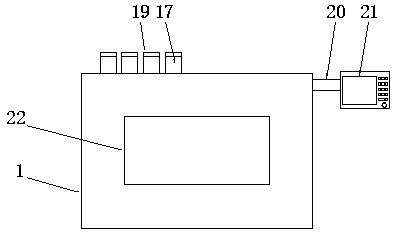
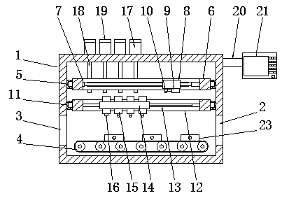
[0031] See Figure 1-2 , an intelligent laser barbecue device, including a box body 1, the bottom of the inner cavity of the box body 1 is provided with a transmission mechanism 4, and the left and right side ends of the box body 1 are respectively connected with discharge holes 3 matched with the transmission mechanism 4 and feed hole 2, several baking pans 23 are placed on the conveying mechanism 4, and a first longitudinal feed mechanism 5 and a second longitudinal feed mechanism 11 are provided on the upper part of the inner cavity of the box body 1. Longitudinal feed mechanism 5 is arranged on the top of second longitudinal feed mechanism 11, and first mobile frame 6 is installed on the first longitudinal feed mechanism 5, and described first mobile frame 6 is a rectangular frame structure, and first mobile frame 6 A first infeed mechanism 7 is arranged inside, and a first moving seat 8 is installed on the first infeed mechanism 7, and a laser generator 9 is fixedly insta...
Embodiment 2
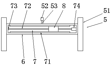
[0037] See image 3 , the difference from Embodiment 1 is that the first longitudinal feed mechanism 5 includes a first electric telescopic rod 52 and two first chute 51, and the two first chute 51 are symmetrically arranged in the box The left and right sides of the inner cavity of the body 1, the first moving frame 6 is slidably connected in front of the two first slide grooves 51, the first electric telescopic rod 52 is fixedly installed on the inner cavity rear wall of the box body 1, the second The movable end of the first telescopic rod 53 on an electric telescopic rod 52 is fixedly connected to the rear side end of the first mobile frame 6, and the first electric telescopic rod 52 is connected with the control panel 21, and is extended by the first electric telescopic rod 52. Extending or withdrawing the first telescopic rod 53 can realize the forward and backward movement of the first moving frame 6 , and then realize the forward and backward movement of the laser gene...
Embodiment 3
[0040] See Figure 4 , the difference from Embodiment 1 is that the second longitudinal feed mechanism 11 includes a second electric telescopic rod 112 and two second chute 111, and the two second chute 111 are symmetrically arranged in the box On the left and right side walls of the inner cavity of the body 1, the second moving frame 12 is slidably connected in two second slide grooves 111, and the second electric telescopic rod 112 is fixedly installed on the inner cavity rear wall of the box body 1, The movable end of the second telescopic rod 113 on the second electric telescopic rod 112 is fixedly connected to the rear end of the second movable frame 12, and the second electric telescopic rod 112 is connected with the control panel 21, and is pushed out or retracted by the second electric telescopic rod 112 The second telescopic rod 113 then pushes the second moving frame 12 to move along the front and rear directions of the second chute 111 , thereby realizing the moveme...
PUM
 Abstract
Description
Claims
Application Information
 - R&D
- Intellectual Property
- Life Sciences
- Materials
- Tech Scout
- Unparalleled Data Quality
- Higher Quality Content
- 60% Fewer Hallucinations
Browse by: Latest US Patents, China's latest patents, Technical Efficacy Thesaurus, Application Domain, Technology Topic, Popular Technical Reports.
© 2025 PatSnap. All rights reserved.Legal|Privacy policy|Modern Slavery Act Transparency Statement|Sitemap|About US| Contact US: help@patsnap.com


