Control Arms and Double Wishbone Suspension
A technology for controlling arms and yokes, applied in suspension, transportation and packaging, cantilevers mounted on pivots, etc., can solve problems such as cost increase and resource waste
- Summary
- Abstract
- Description
- Claims
- Application Information
AI Technical Summary
Problems solved by technology
Method used
Image
Examples
Embodiment 1
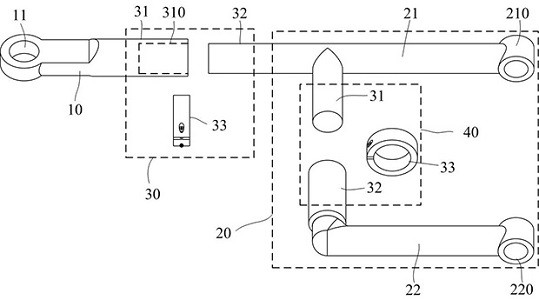
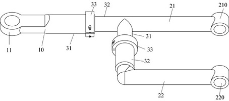
[0032] see figure 1 and figure 2 As shown, this embodiment provides a control arm 100 , which mainly includes: a connecting arm body 10 , a yoke body 20 , a length adjustment mechanism 30 , and a distance adjustment mechanism 40 . In order to clearly express the composition of each structure, figure 1 Use the dotted line frame to select the approximate range of the yoke body 20, the length adjustment mechanism 30, and the distance adjustment mechanism 40. The connecting arm body 10 is used to connect with the steering knuckle, and the yoke body 20 is used to connect with the vehicle frame. The distance between the connecting arm body 10 and the yoke body 20 can be adjusted by the length adjustment mechanism 30 to change the length of the control arm. , to meet the design requirements of different wheelbases in different models, the distance between the two arms in the yoke body 20 can be changed through the distance adjustment mechanism 40, so as to change the distance betw...
Embodiment 2
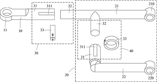
[0049] This embodiment provides a control arm. The only difference between the control arm 100 and the first embodiment is that a deformation groove is formed on the cylindrical extension wall 31 so that the cylindrical extension wall 31 can be deformed greatly. see image 3 and Figure 4 A deformation groove 311 penetrating through the thickness of the cylindrical extension wall 31 is opened on the wall body of the cylindrical extension wall 31 along the length direction of the cylindrical extension wall 31 . More specifically, a plurality of deformation grooves 311 can be provided on the cylindrical extension wall 31 , and after the locking sleeve 33 is sleeved on the outer wall of the cylindrical extension wall 31 , by locking the fastener 333 , the The cylindrical extension wall 31 can produce relatively large deformation, and can effectively lock the plug-in section.
Embodiment 3
[0051] The difference between this embodiment and Embodiment 1 and Embodiment 2 lies in the length adjustment mechanism and the distance adjustment mechanism. In this embodiment, the structures of the length adjustment mechanism and the distance adjustment mechanism are also the same. For the convenience of description, this embodiment The example only describes the structures of the length adjustment mechanism and the distance adjustment mechanism, and the same reference numerals are used to indicate the components of the length adjustment mechanism and the distance adjustment mechanism in the drawings.
[0052] see Figure 5 and Figure 6 as shown, Figure 5The approximate range of the middle fork arm body 20, the length adjustment mechanism 30, and the distance adjustment mechanism 40, the length adjustment mechanism 30 and the distance adjustment mechanism 40 all include: a connecting piece 34, which has a first connecting section 341 and a second connecting section 342 ...
PUM
 Abstract
Description
Claims
Application Information
 - R&D
- Intellectual Property
- Life Sciences
- Materials
- Tech Scout
- Unparalleled Data Quality
- Higher Quality Content
- 60% Fewer Hallucinations
Browse by: Latest US Patents, China's latest patents, Technical Efficacy Thesaurus, Application Domain, Technology Topic, Popular Technical Reports.
© 2025 PatSnap. All rights reserved.Legal|Privacy policy|Modern Slavery Act Transparency Statement|Sitemap|About US| Contact US: help@patsnap.com


