Embedded type stealth air inlet channel
An air inlet, buried technology, applied in the field of aircraft stealth, can solve the problems of increased weight and high cost, and achieve the effect of reducing forward radar echo, avoiding structural weight gain and cost increase
- Summary
- Abstract
- Description
- Claims
- Application Information
AI Technical Summary
Problems solved by technology
Method used
Image
Examples
Embodiment 1
[0042] Step 1: Parametric modeling of the shape of the intake port
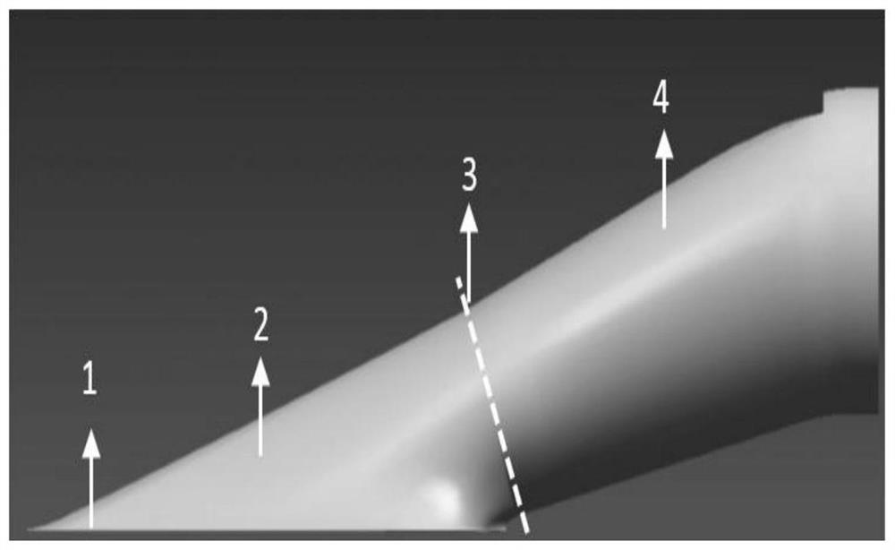
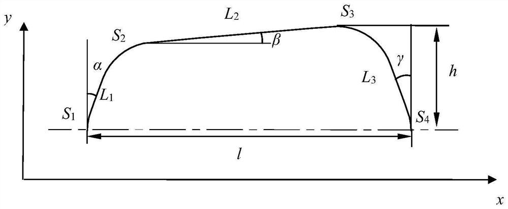
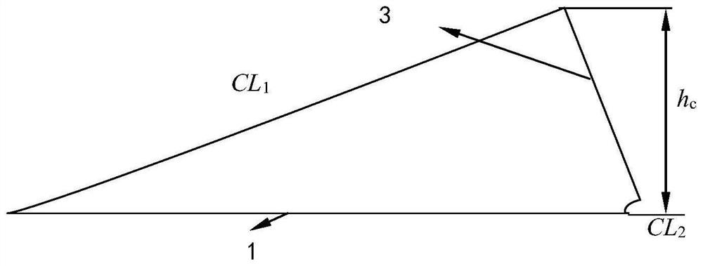
[0043] According to the project requirements and constraints, sweep the minimum section 3 of the intake duct and the lip 1 area, generate the minimum section 3 line of the intake duct and the basic contour line of the lip 1, and set S 1 , S 2 , S 3 , S 4 , L 1 , L 2 , L 3 , α, β, γ and other parameters, where α, γ take 20°, S 1 , S 2 , S 3 , S 4 Both are tangent fillets. The shape of the inlet lip 1 is constrained by the total length l of the lip 1 and the total width h of the lip 1. The l is taken as 450 mm, and the h is taken as 147 mm to obtain the shape of the quasi-hexagonal lip 1; according to the curve of the lip 1 and the minimum section 3 line, generate channel import segment 2 longitudinal line, set cl 1 、CL 2 and other parameters; sweep the outlet section 4 of the inlet duct to generate the longitudinal line and the section line of the outlet section 4 of the channel. The inner surface...
Embodiment 2
[0053] Step 1: Parametric modeling of the shape of the intake port
[0054] According to the project requirements and constraints, sweep the minimum section 3 of the intake duct and the lip 1 area, generate the minimum section 3 line of the intake duct and the basic contour line of the lip 1, and set S 1 , S 2 , S 3 , S 4 , L 1 , L 2 , L 3 , α, β, γ and other parameters, where α takes 75°, γ takes 20°, S 1 , S 2 , S 4 Both are tangent fillets, L 2 , S 3 , β are both taken as 0, the shape of the inlet lip 1 is constrained by the total length l of the lip 1 and the total width h of the lip 1, l is taken as 525mm, and h is taken as 155mm, and the outer shape of the lip 1 is obtained as a triangular shape; according to the curve of the lip 1 and minimum section 3 lines, generate channel inlet section 2 longitudinal lines, set CL 1 、CL 2 and other parameters; sweep the outlet section 4 of the inlet duct to generate the longitudinal line and the section line of the outle...
Embodiment 3
[0065] Step 1: Parametric modeling of the shape of the intake port
[0066] According to the project requirements and constraints, sweep the minimum section 3 of the intake duct and the lip 1 area, generate the minimum section 3 line of the intake duct and the basic contour line of the lip 1, and set S 1 , S 2 , S 3 , S 4 , L 1 , L 2 , L 3 , α, β, γ and other parameters, where L 1 , L 2 , L 3 Take 0, S 1 , S 2 , S 3 , S 4 Both are tangential transitions. The shape of the inlet lip 1 is constrained by the total length l of the lip 1 and the total width h of the lip 1. The l is taken as 550 mm, and the h is taken as 550 mm to obtain the shape of the oval lip 1; according to the lip 1 Curve and minimum section 3 lines, generate channel inlet section 2 longitudinal lines, set CL 1 、CL 2 and other parameters; the outlet section of the inlet is swept, and the longitudinal line and the section line of the outlet section 4 of the channel are generated. The inner surface...
PUM
 Abstract
Description
Claims
Application Information
 - R&D
- Intellectual Property
- Life Sciences
- Materials
- Tech Scout
- Unparalleled Data Quality
- Higher Quality Content
- 60% Fewer Hallucinations
Browse by: Latest US Patents, China's latest patents, Technical Efficacy Thesaurus, Application Domain, Technology Topic, Popular Technical Reports.
© 2025 PatSnap. All rights reserved.Legal|Privacy policy|Modern Slavery Act Transparency Statement|Sitemap|About US| Contact US: help@patsnap.com


