Shifting fork reversing structure of intelligent vehicle for seeding wall

A technology for planting walls and smart vehicles, applied in mechanical conveyors, transportation and packaging, conveyors, etc., can solve problems such as fork fragility, and achieve the effect of improving stability and work efficiency

Pending Publication Date: 2022-01-07
中科微至科技股份有限公司
6 Cites 0 Cited by

AI-Extracted Technical Summary

Problems solved by technology

[0003] In the existing technology, the shift fork structure has the disadvantage of strong working stability; in addition, in order to achieve the purpose of noise reduction,...

Abstract

The invention relates to a shifting fork reversing structure of an intelligent vehicle for a seeding wall, which is mounted at two ends of a horizontal conveying section of the intelligent vehicle of a seeding wall frame. The shifting fork reversing structure comprises a driving device, a crank, a rocker, a rotating shaft, a bearing fixing seat and a toothed special-shaped shifting fork, the rotating shaft is rotationally mounted on the bearing fixing seat, one end of the rotating shaft is fixedly connected with the rocker, and the other end of the rotating shaft is connected with the upper end of the toothed special-shaped shifting fork; the output end of the driving device is fixedly connected with one end of the crank, and a follower is mounted at the other end of the crank; the rocker is provided with two deflector rods, and the follower on the crank is located between the two deflector rods; conveying teeth are arranged on the outer side of the toothed special-shaped shifting fork, and the upper end and the lower end of the toothed special-shaped shifting fork are connected with the lifting conveying section when the toothed special-shaped shifting fork is in a vertical state; and the toothed special-shaped shifting fork rotates towards the outer side and can avoid the space for the intelligent trolley to pass through. According to the shifting fork reversing structure of the intelligent vehicle for the seeding wall, the function of trolley sorting and reversing can be achieved, and the working stability and working efficiency of the whole sorting system are improved.

Application Domain

Mechanical conveyors

Technology Topic

CrankRotational axis +2

Image

  • Shifting fork reversing structure of intelligent vehicle for seeding wall
  • Shifting fork reversing structure of intelligent vehicle for seeding wall
  • Shifting fork reversing structure of intelligent vehicle for seeding wall

Examples

  • Experimental program(1)

Example Embodiment

[0018] In order to make the above objects, features and advantages of the present invention more comprehensible, the specific implementation manners of the present invention will be further described below in conjunction with specific drawings.
[0019] In the following description, a lot of specific details are set forth in order to fully understand the present invention, but the present invention can also be implemented in other ways that are different from those described here, and those skilled in the art can do so without departing from the connotation of the present invention. By analogy, the present invention is not limited by the specific examples disclosed below.
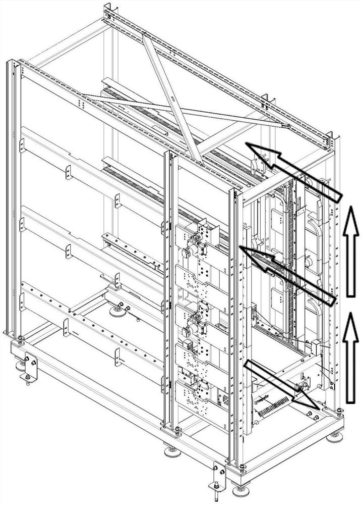
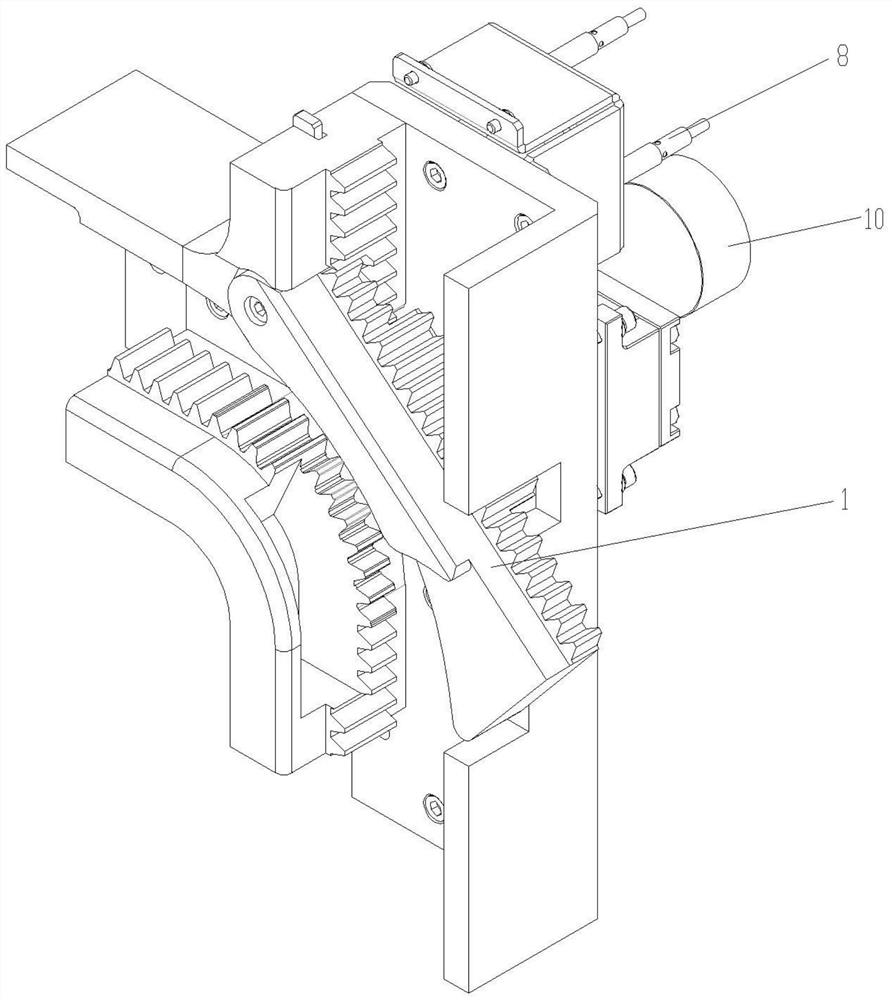
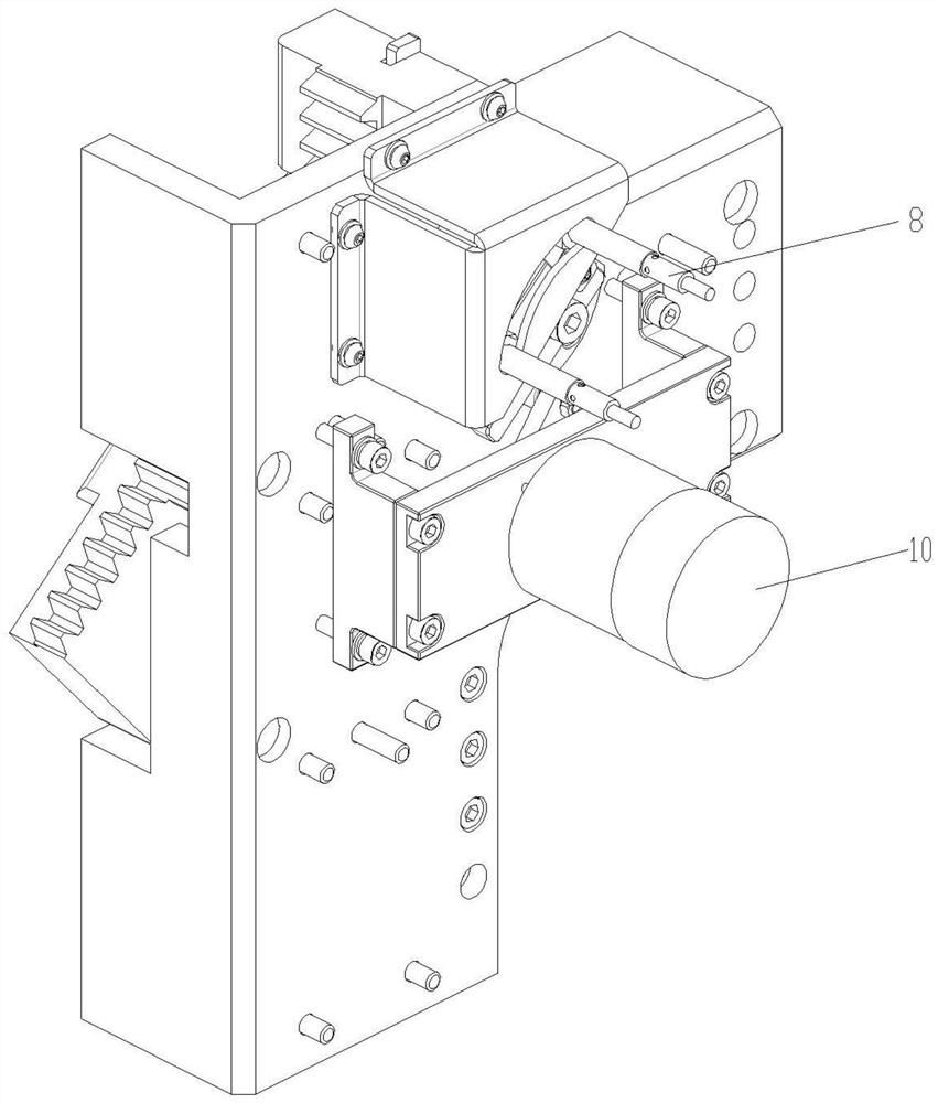
[0020] The switching fork reversing structure of the smart car of the planting wall of the present invention, such as figure 1 As shown, the two ends of the horizontal conveying section of the smart trolley installed on the planting wall frame; Figure 2-Figure 4 As shown, the shift fork reversing structure includes a driving device 10, a crank 3, a rocker 4, a rotating shaft 2, a bearing fixing seat 5 and a toothed special-shaped shift fork 1; the rotating shaft 2 is rotatably installed through a flange bearing 6 On the bearing holder 5, one end of the rotating shaft 2 is fixedly connected with the rocking bar 4, and the rocking bar 4 rotates around the rotating shaft 2, and the other end of the rotating shaft 2 is connected with the upper end of the special-shaped shift fork 1 containing teeth; The driving device 10 on the bearing holder 5 adopts a rotating electromagnet or a servo motor, and the output end of the driving device 10 is connected to one end of the crank 3, and the follower 7 is installed on the other end of the crank 3; There are two levers on the top, and the follower 7 on the crank 3 is located between the two levers. When the crank 3 is driven by the driving device 10 to rotate, the follower 7 drives the rocker 4 to move between the left and right positions. The outer side of the tooth-containing special-shaped shift fork 1 is a conveying tooth. When the tooth-containing special-shaped shift fork 1 is in a vertical state, the upper and lower ends of the tooth-containing special-shaped shift fork 1 are respectively connected with the conveying teeth of the lifting conveying section of the smart car to form a A complete lifting conveying section; when the toothed special-shaped shift fork 1 is driven by the drive device 10 to rotate outward, the inner side of the toothed special-shaped shift fork 1 avoids the space that allows the smart car to pass, and the smart car turns along the lifting conveying section to Horizontal conveying section; at the same time, the inner side of the tooth-containing special-shaped shift fork 1 matches the corner at the junction of the lifting conveying section and the horizontal conveying section, so as to ensure that the tooth-containing special-shaped shift fork 1 does not collide with the corner when it is in a vertical state. put one's oar in.
[0021] like figure 2 As shown, a notch is provided on the frame on one side of the toothed special-shaped shift fork 1 for avoiding the toothed special-shaped shift fork 1 that rotates outward.
[0022] like image 3 , Figure 4 As shown, the rocker 4 is provided with a proximity switch stopper 9, and two proximity switches 8 are installed on the bearing holder 5, and the two proximity switches 8 are respectively positioned at the vertical and vertical positions of the toothed special-shaped shift fork 1. The two positions after the rotation are matched by the proximity switch catch 9 and the pull-in switch 8 to indicate the two positions.
[0023] like figure 1 As shown, the route direction of the smart car when walking in the sowing wall. When a reversing signal occurs in the whole equipment system, the driving device 10 drives the crank 3 to rotate, and the other end of the crank shakes the rocker 4 and the rotating shaft 2, and transmits the power to the toothed special-shaped shift fork 1, thereby realizing the toothed special-shaped shift fork 1 to reversing, to complete the tooth-containing special-shaped shift fork 1 to rotate outward from the vertical state, thereby avoiding the steering space of the smart car.
[0024] The fork reversing structure of a planting wall smart car provided by this application has been introduced in detail above. In this paper, specific examples are used to illustrate the principle and implementation of this application. The description of the above embodiments is only for helping understanding The method of this application and its core idea; at the same time, for those of ordinary skill in the art, according to the idea of ​​this application, there will be changes in the specific implementation and scope of application. In summary, the content of this specification should not understood as a limitation of the application.

PUM

no PUM

Description & Claims & Application Information

We can also present the details of the Description, Claims and Application information to help users get a comprehensive understanding of the technical details of the patent, such as background art, summary of invention, brief description of drawings, description of embodiments, and other original content. On the other hand, users can also determine the specific scope of protection of the technology through the list of claims; as well as understand the changes in the life cycle of the technology with the presentation of the patent timeline. Login to view more.

Similar technology patents

Output current control circuit, system and method

PendingCN113490301AImprove work efficiency and stability
Owner:深圳市海洋王石油照明技术有限公司 +3

Automatic equipment applied to ultraviolet LED lamp processing

PendingCN113499946AImprove injection efficiencyImprove work efficiency and stability
Owner:ZHONGSHAN MULINSEN ELECTRONICS CO LTD

Pesticide sprayer with balance control function

InactiveCN107020908AImprove work efficiency and stabilityResponsive
Owner:管中林

Laser resistor trimming machine control device

ActiveCN102509599AImprove work efficiency and stabilityImprove anti-interference
Owner:沈玉良

Real-time protection device for multi-path full-bridge inversion module

ActiveCN106160443Asimple circuitImprove work efficiency and stability
Owner:NANJING PERLOVE RADIAL VIDEO EQUIP

Classification and recommendation of technical efficacy words

  • Improve work efficiency and stability

Sand mold casting system for conveniently cleaning finished sand mold

ActiveCN108746515AThe process is compact and efficientImprove work efficiency and stability
Owner:黄斌 +2

Pesticide sprayer with balance control function

InactiveCN107020908AImprove work efficiency and stabilityResponsive
Owner:管中林

Real-time protection device for multi-path full-bridge inversion module

ActiveCN106160443Asimple circuitImprove work efficiency and stability
Owner:NANJING PERLOVE RADIAL VIDEO EQUIP

Laser resistor trimming machine control device

ActiveCN102509599AImprove work efficiency and stabilityImprove anti-interference
Owner:沈玉良

Automatic equipment applied to ultraviolet LED lamp processing

PendingCN113499946AImprove injection efficiencyImprove work efficiency and stability
Owner:ZHONGSHAN MULINSEN ELECTRONICS CO LTD
Why Eureka
Try Eureka